
Subwoofer filter schematic

Parts List:
- R1, R2 = 47 kOhm
- R3, R4 = 4.7 kOhm
- R5, R6 = 100 Ω
- P1 = 47 kOhm logarithmic
- C1-C3 = 100 nF
- IC1, IC2 = LM 741
The described circuit functions as a dedicated low-pass filter specifically designed to enhance the bass response in audio systems. The active filter configuration utilizes operational amplifiers to achieve better performance than traditional passive filters. The use of the LM741 operational amplifier allows for adjustable gain, enabling users to tailor the bass output to their preferences.
The first stage of the circuit employs the LM741 as a mixing amplifier, with the gain controlled by a logarithmic potentiometer (P1). This configuration allows for precise adjustments to the input signal level before filtering. The output from the mixing amplifier is then routed to the Butterworth low-pass filter, which is designed to allow frequencies below the crossover frequency (set at 240 Hz) to pass while attenuating higher frequencies.
Capacitors C1 and C2 are combined to form C_A, while C3 serves as C_B in the filter design. The cutoff frequency can be adjusted by varying the values of the resistors (R3 and R4) and capacitors (C1, C2, and C3) according to the established formulas.
The circuit requires a dual power supply, providing both positive and negative voltages in the range of 12-15 V, ensuring the operational amplifiers function correctly. For applications requiring superior audio fidelity, replacing the LM741s with NE5532 operational amplifiers is recommended, as the NE5532 offers lower noise and better performance characteristics.
The provided parts list specifies the necessary components for constructing the circuit, ensuring users can source the appropriate values for resistors and capacitors. The layout specifications indicate a printing resolution of 150 dpi for accurate representation of the circuit design in a compact form. This design caters to audio enthusiasts seeking to enhance their listening experience with improved bass response through an effective and adjustable electronic filter solution.If you like me more bass in your stereo like, you can turn a subwoofer there. This is a speaker that only the bass frequencies. Below is a circuit to ensure that the subwoofer is really only the bass gets. The circuit between the signal source (mixer, CD player) and the amplifier used. It is an active filter, which is usually better than passive filters are installed after the amplifier. The circuit is mono because the bass for both channels are equal. The human ear can in these notes do not provide direction. The first 741 is used as a mixing amplifier. The gain is adjustable with P1. Then the signal is fed to February 1 the order Butterworth filter. C A (C1 + C2) and C B (C3) are to be calculated using the following formulas: Here, F k the crossover frequency (frequency where the filter stops the passage of sound), pi = 3.1416, R = R3 = R4, F k in Hertz, C and F. As drawn, the filter is now set to 240 Hz. The supply voltage should be symmetric, + and - 12-15 V. An appropriate nutrition is the minimum power symmetric . If you want a better sound quality would have two 741's can be replaced by an NE5532. The picture for the layout should be printed at 150dpi (= + / - 33x33mm). Parts List R1, R2 = 47 kOhm R3, R4 = 4.7 kOhm R5, R6 = 100 ? P1 = 47 kOhm logarithmic C1-C3 = 100 nF IC1, IC2 = LM 741 🔗 External reference
Related Circuits
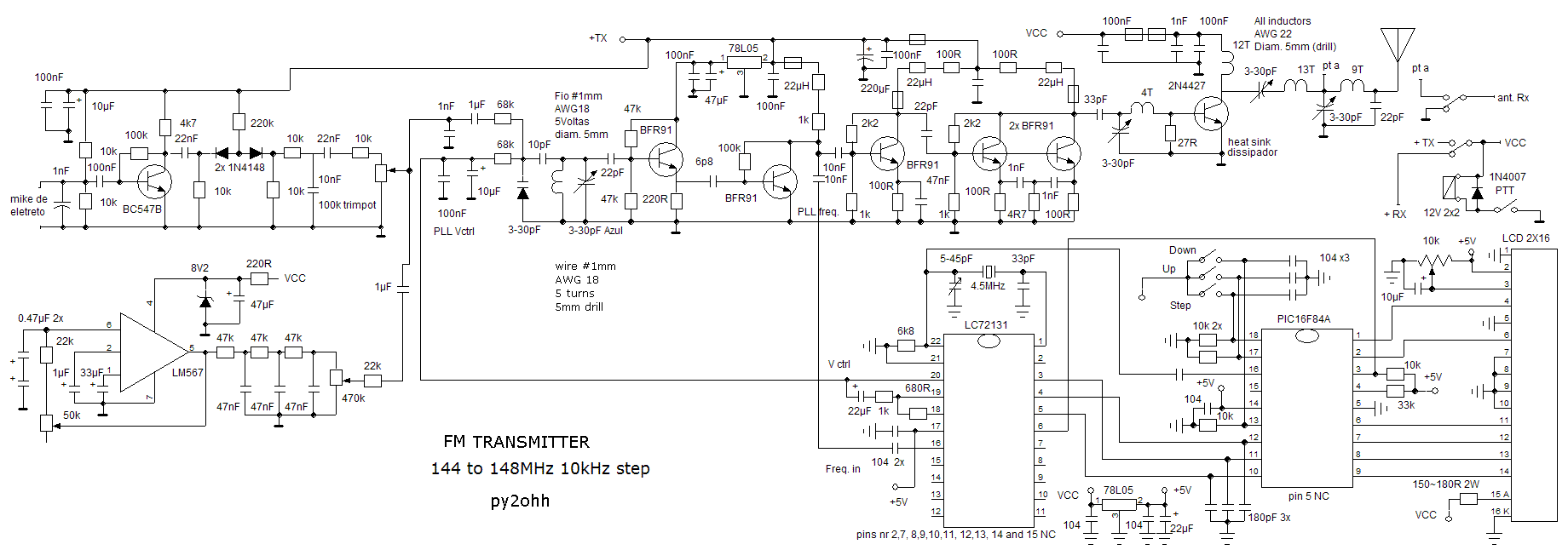
Another version of the 1W VHF amplifier for the FM transceiver is presented. It is essentially the same version since achieving 1W output power has not yet been realized. Recent tests were conducted using a 2N2553 and a 2N2866...
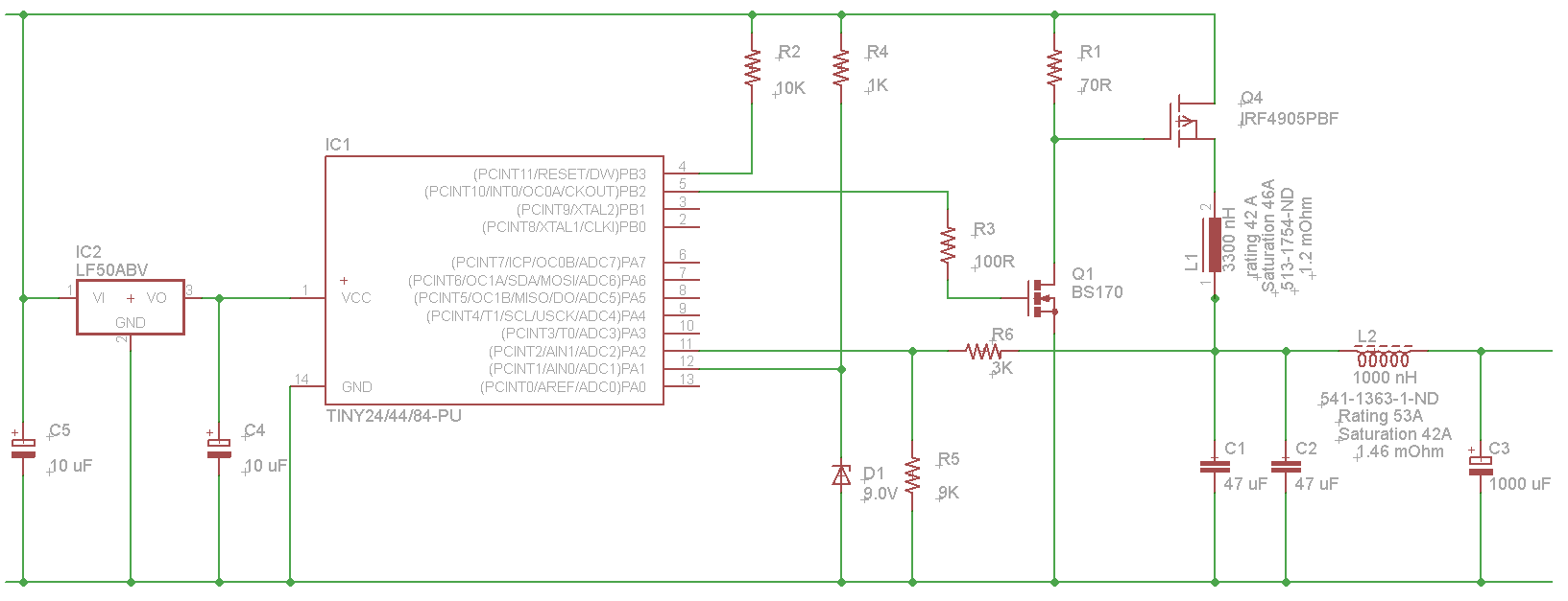
The microcontroller will not be able to drive the gate of Q1 effectively, as GPIO pins typically can only source a few milliamps, resulting in slow turn-on and turn-off times. This limitation will affect the performance of the high-side...
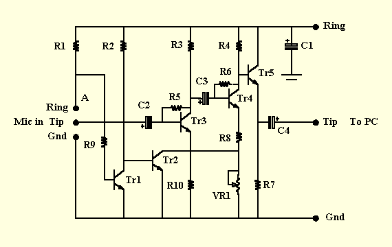
This is a microphone preamplifier designed for compatibility with a SoundBlaster AWE 64 sound card. It is also suitable for any compatible tag or PC audio input that provides a 5 Volt supply through a 2.2kΩ current-limiting resistor located...
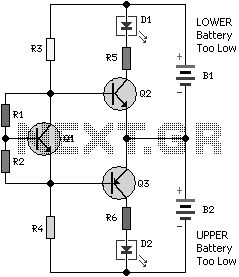
Almost all 24V power systems in trucks, 4WDs, RVs, boats, etc., utilize two series-connected 12V lead-acid batteries. The charging system can only sustain the total voltage of the individual batteries. If one battery is failing, this circuit will illuminate...
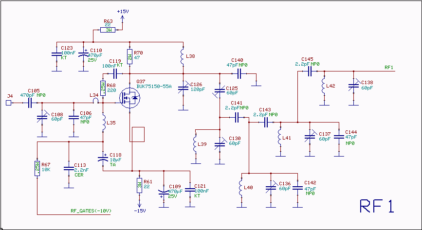
The RF amplifier utilizes noiseless feedback via the drain-gate capacitance, incorporating an inductor in the source lead to achieve the required 90-degree phase shift between the gate voltage and channel current. The RF amplifier is designed to enhance signal strength...
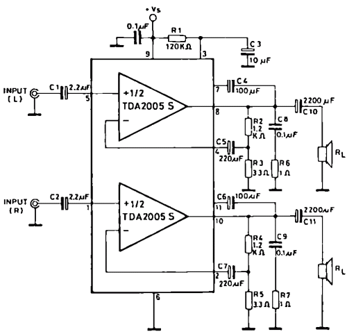
The TDA2005 integrated circuit (IC) features a high output power of 10W per channel (stereo) at a load of 2 ohms with a distortion of 10%, and 20W in bridge mode at a load of 4 ohms with a...