
NiCd battery ChargerCircuit With TLC555 IC

The portable NiCd battery charger circuit typically consists of several key components, including a transformer, rectifier, voltage regulator, and charging indicator. The transformer steps down the AC voltage from the mains supply to a lower AC voltage suitable for charging the battery.
The rectifier, often implemented with diodes, converts the AC voltage into pulsating DC voltage. This pulsating DC is then smoothed out using capacitors to provide a more stable DC output. A voltage regulator is employed to ensure that the output voltage remains constant, preventing overcharging which could damage the battery.
The charging process is monitored using an LED indicator, which lights up to indicate that the charging is in progress. The circuit may also include a resistor to limit the current flowing into the battery, thus protecting it from excessive charging current.
In addition to these components, the circuit may feature a switch to allow the user to turn the charger on or off as needed. Safety features such as thermal fuses or cutoff circuits can also be integrated to enhance the reliability of the charger, ensuring that it operates within safe temperature limits.
Overall, this portable NiCd battery charger circuit provides a practical solution for charging batteries in various applications, making it an essential tool for users of portable electronic devices.The following circuit shows a Portable NiCd battery charger ciecuit diagram. The portable batteries charger used to provide an opportunity to load .. 🔗 External reference
Related Circuits
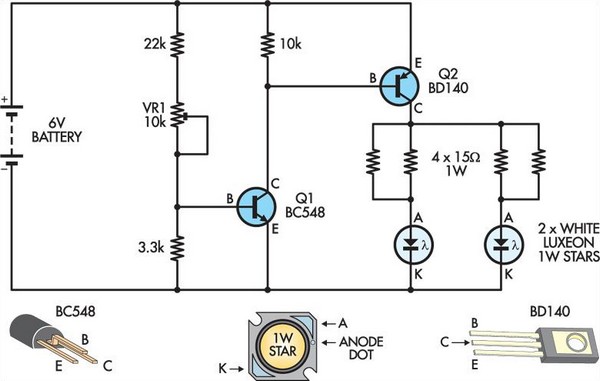
This circuit replaces two white Luxeon 1W Star LEDs for the inverter and fluorescent tube in a standard battery-powered illuminated exit sign, commonly found in commercial buildings. Although the Luxeon LEDs produce less light output than a typical small...
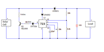
The ultimate source of energy is the Sun. It is possible to generate current from sunlight using solar panels. These panels convert light energy into electrical energy. A solar panel consists of a number of solar cells, which produce...
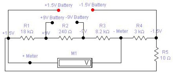
The circuit diagram of a DC battery tester designed by Matthew B. This circuit can measure DC batteries ranging from 1.5V to 9V. Component Parts List: R1 = 18K Ohm, R2 = 240 Ohm, R3 = 8.2K Ohm, R4...
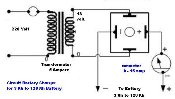
The circuit diagram of a simple and straightforward 12 V battery charger is presented here. This circuit can be utilized to charge various types of 12V rechargeable batteries, including car batteries and motorcycle batteries. The 12 V battery charger circuit...
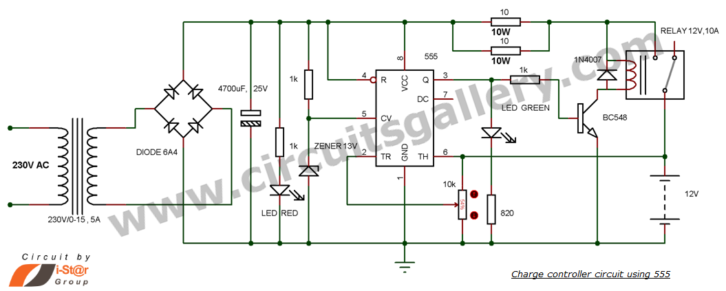
This is a simple DIY charge controller schematic created in response to a request from one of the readers on our Facebook page. The primary component of this automatic battery charger circuit is a 555 timer, which compares the...
There are two differing opinions regarding the charging of alkaline batteries. Some assert that charging is effective, while others caution against it due to the risk of explosion. It is acknowledged that rechargeable alkaline batteries can typically endure 30...