
NiCd NiMH Battery Charger
This schematic diagram showcases a versatile battery charging solution, accommodating various types of rechargeable batteries. The Ni-CAD charger is particularly designed to maintain battery health through effective current and voltage regulation. The inclusion of lamp L1 serves as a visual indicator of charging status, enhancing user awareness of the charging process. The LED's behavior provides additional feedback, indicating when the battery is in a low state and actively charging.
The circuit's design for multi-cell packs allows for flexibility in battery configurations, supporting 2 to 6 cells in series, which is essential for applications requiring higher voltages. The specified charging current of 60 mA for AA cells ensures that the batteries are charged safely without overheating, while the cutoff voltage of 2.4V is critical for preventing overcharging, which can lead to reduced battery life or damage.
The 12V Ni-CAD charger operates effectively at a charging rate of 200 mA per hour, with the ability to reduce the charging current to a trickle rate once the battery reaches full charge. This feature is particularly beneficial for maintaining battery health over extended periods without causing damage due to overcharging.
The lead-acid battery charger circuit is optimized for rapid charging with an initial voltage of 2.5V per cell, suitable for quick recovery of depleted batteries. The automatic reduction of charging current as the battery approaches full charge is a key safety feature that prevents excessive current flow, thereby enhancing the longevity of the battery.
The solar-powered mobile phone battery charger is designed to leverage renewable energy sources, making it an environmentally friendly option. The design considerations ensure that it operates effectively only with compatible voltage levels, preventing potential damage to the batteries being charged.
Overall, this comprehensive battery charging circuit design is adaptable to various battery technologies and configurations, providing a robust solution for both consumer and industrial applications. The integration of adjustable regulation and safety features makes it suitable for a wide range of battery management scenarios.The following diagram is the schematic diagram of Ni-CAD Battery Charger circuit which featured with current and voltage limiting to keep the battery lifetime. The lamp L1 will be light brightly and the LED will be out when the battery is low and battery charging in progress, but the LED is very bright and the.
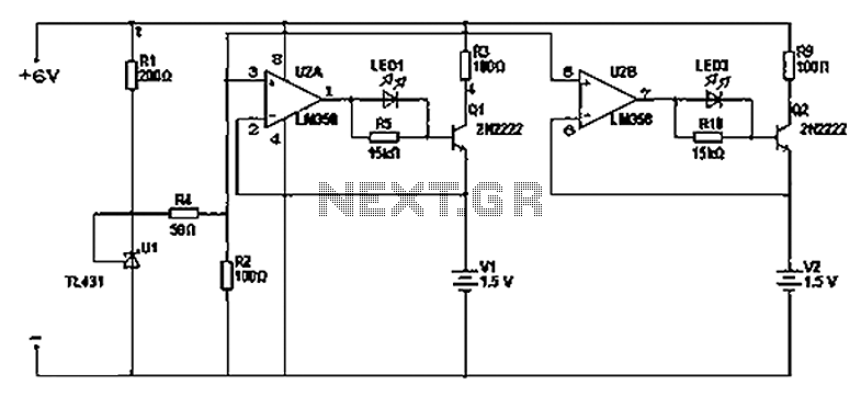
This battery charger circuit is use d for rechargable lithium battery. Charging is accomplished with a constant current of 60 mA for AA cells to a cutoff of 2. 4V per cell, at which point the charge must be terminated. The charging system shown is designed for multi-cell battery pack of 2 to 6 series connected cell. The following diagram is the schematic diagram of 12V NiCAD battery charger with charging rate of 200mA/Hour. This NiCAD battery charger circuit charges the battery at 75 mA until the battery is charged, then it reduces the current to a trickle rate.
It will fully recharge a dead/unpowered battery in 4 hours and the battery. The following diagram is the circuit diagram of Lead-Acid battery charger. This circuit provides an initial voltage of 2. 5 V per cell at 25 ƒ to quickly charge the battery. The charging current decreases as the battery is charging, and when the current drops to 180 mA, the charging circuit reduces the output voltage of. This is the schematic diagram of solar powered mobile phone battery charger. The circuit is designed to charge the battery from a source with a lower voltage. Do not use it to charge the battery with the same or lower voltage than the voltage which is generated by the solar panel.
For proper operation of. This battery charger circuit is regulated and adjustable to make this circuit able to charge the mosto NiCAD battery. This circuit will work for single cell or multi battery cell which connected with series/parallel connection.
The maximum voltage of the batteries should be 18V maximum. Power transistors Q1 and Q2 are connected as series regulators. 🔗 External reference
Related Circuits
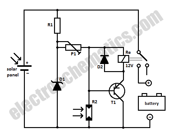
When charging a battery during the day using a solar panel, there is a risk of the battery partially discharging through the panel after sunset. This solar panel power switch circuit eliminates the need for a diode by utilizing...
There are two differing opinions regarding the charging of alkaline batteries. Some assert that charging is effective, while others caution against it due to the risk of explosion. It is acknowledged that rechargeable alkaline batteries can typically endure 30...
MSP430 microcontroller and I2C-compatible slave peripheral device. Temperature measurement tasks can be accomplished in a variety of ways. The MSP430 microcontroller is a low-power, 16-bit device widely used in embedded systems, particularly for applications requiring efficient power management and precise...
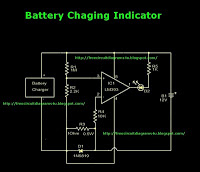
This is a battery charger indicator circuit diagram. When the battery is charging, it is indicated by an LED. This circuit can be used with a 12V battery with a charging current of less than 1A. The battery charger indicator...
Most 24V power systems in trucks, 4WDs, RVs, boats, and similar applications utilize two series-connected 12V lead-acid batteries. The charging system is capable of maintaining the total voltage of the individual batteries. If one battery is experiencing failure, this...
This circuit utilizes the widely available LM3914 integrated circuit (IC). The LM3914 is straightforward to operate, does not require external voltage regulators due to its built-in voltage regulation, and can be powered by a variety of sources. The LM3914 is...