
Nixie Clock Version 1
The circuit design for this nixie tube clock utilizes a combination of logic ICs and transistors to create a functional timekeeping mechanism. The primary components include the Burroughs B-5560 nixie tubes, which display numerical values through the application of high voltage. The use of 4017 decade counters facilitates the counting of seconds, minutes, and hours, while ensuring that the display increments correctly and resets after reaching their maximum values.
To enhance reliability, the circuit incorporates a voltage doubler configuration, which is critical for generating the necessary high voltage to drive the nixie tubes. The transformerless design, while compact, requires careful consideration of insulation and safety, particularly where user interaction occurs via the time-setting switches. The alternating display design allows for a visually dynamic representation of time, achieved by selectively grounding the transistors associated with either the hour or minute display.
The implementation of ribbon cable connections between the controller and the display board is notable for its compactness but presents unique challenges in assembly. The use of 4013 and 4017 ICs for buffering and counting ensures that the clock maintains accurate timing, with the ability to reset and reinitialize through user interaction. Overall, this clock circuit exemplifies innovative use of digital logic and analog components to achieve a functional and visually appealing timekeeping device.The clock was experimental until I picked up some experience with the circuitry. I experimented with the idea of building an alternating display using two B-5560 nixie tubes but ended up using 4 nixies instead. The original idea was to display the hours, then minutes, then the cycle starts again. The nixie tubes used in this clock are Burroughs B-5560 tubes that were salvaged from a small broken HP frequency counter.
Those nixie tubes are mounted upside down and required a separate board to hold the nixie tubes and cathode transistors. The alternating display idea was to wire the collector ends of the 1 hour transistors to the 1 minute transistors and the 10 hour transistor (I did not use zero for the 10 hours at first) to a 10 minute transistor (only a digit 1 from the 10 hour).
The emitter ends of the hour transistors were tied and separate from the tied emitter ends of the minute transistors. This meant I could feed in the signals to all the transistors as if all nixies were present, but one set of transistors` (hours or minutes) emitter ends would be grounded.
Therefore, displaying only the hours or the minutes, if both sets of transistors were connected and grounded, the digits would overlap. I spent about a day wiring the board with the two nixies and the 27 transistors. I used a ribbon computer cable to carry the signals from the controller board to the switching transistors.
It was very difficult to wire the ribbon cable to the two boards since most of the connections are thin and I was using a dull soldering iron. After the first board was completed and wired, I started on the controller board. I had problems with the hours not resetting correctly so I used another 4017 IC instead. I also used another 4017 IC for the 10 hour IC instead of the other 4013 half so I can display zero with my single digit hours (for example; 03:00, not 3:00 with the 10 hour nixie appearing dead).
I started on the power supply for both the nixies and controller board. This is the dangerous part of the overall design. A voltage doubler is used to provide HV to drive the nixies and the HV is also reduced to a few volts for the ICs. The power supply is transformerless so some parts of the circuit can be hot. The two time set switches need reasonably good insulation from the circuitry such as my simple long-pole pushbutton switches salvaged from a VCR.
A half of a 4013 IC was used to buffer the 60Hz line. Four 4017 ICs were used to divide the 60Hz line signal to 1/60Hz so you would have to wait 60 seconds for the fourth IC to toggle the 1 minute IC. The other three 4017 ICs are used as counters for the display. The 10 minute IC is wired differently because when it counts to the 7th output (digit 6), that output feeds a signal to the reset trigger to reset the count back to zero.
So when the 10 minute counts to 6 (60 minutes) then it resets to 0. The hours IC is a little more tricky. The 1-hour IC starts the display at the digit 1, and counts up to 9, then 0. At the 10th output, the 10 hours IC is incremented from 0 to 1. Also, when the 1-hour IC passes through 3:00 it increments another 4017 used for reset. The second time around when the hours goes from 12 to 13, the 4017 increments and resets itself and both 4017s for the hours display back to 1:00. When powering up, the clock will normally display incorrect time, overlapping digits or even count incorrectly.
This is normal because the 4017 ICs often power up in odd states. This can be fixed by holding down the fast set button for about 10 to 15 seconds until the clock functions correctly with all the counters resetting themselves back into the expected range of states. After that, you can set the time. 🔗 External reference
Related Circuits
The MCU is an ATMEL 89C4051 CMOS Microcontroller featuring 4kB of code memory, 128 bytes of on-chip RAM, and 8-bit Port1 and Port3. The A/D chip is a HARRIS CA3162, which functions as a 3-digit digital voltmeter (DVM). This...
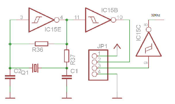
Last year, I found a 31 day pendulum wall clock (disassembled) in a box of parts at a swap meet and decided to try and put it together and regulate it with a quartz crystal oscillator. The escapement part...
This precise one-pulse-per-second clock is constructed using a few common components and is powered by a 50 or 60 Hertz mains supply without any direct connection to it. A beep or metronome-like click, along with a visible flash, indicates...
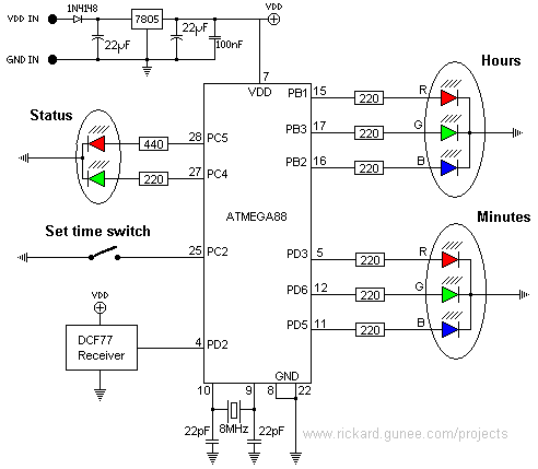
This page describes a color clock that displays the time using two RGB LEDs, one for hours and one for minutes. It uses standard color coding for components, with two additional colors to accommodate the twelve distinct color representations...
More: A comprehensive electronic schematic that outlines the design and functionality of a specific circuit is crucial for understanding its operation. The schematic should include components such as resistors, capacitors, diodes, transistors, and integrated circuits, along with their interconnections....
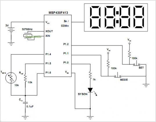
Both specifications were contradictory; a large display would require a significant amount of power, while the intention was to use the smallest battery for the longest duration. The solution was to separate the power supply for the logic and...
Warning: include(partials/cookie-banner.php): Failed to open stream: Permission denied in /var/www/html/nextgr/view-circuit.php on line 713
Warning: include(): Failed opening 'partials/cookie-banner.php' for inclusion (include_path='.:/usr/share/php') in /var/www/html/nextgr/view-circuit.php on line 713