
Nixie-Tube Clock
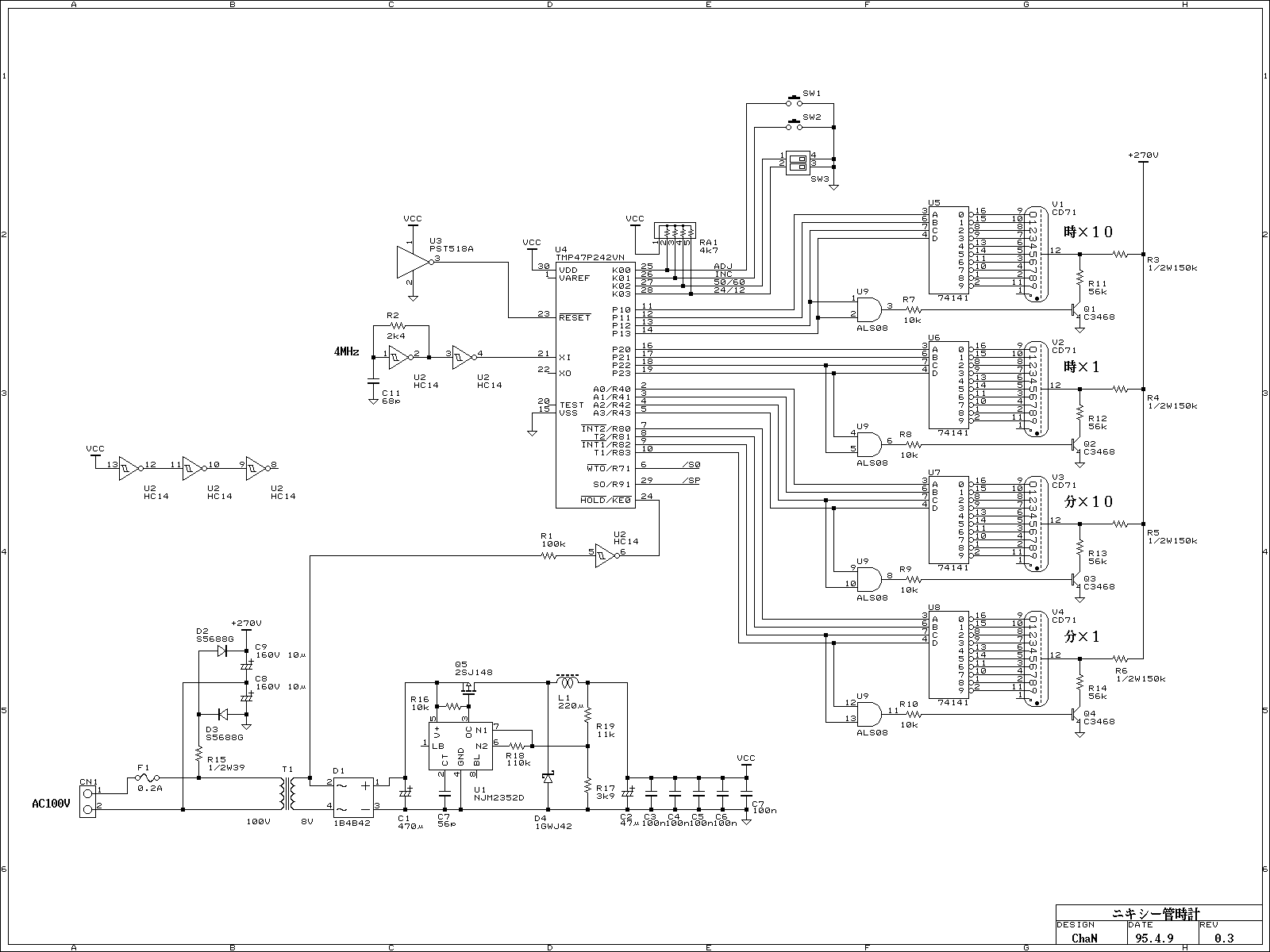
The nixie tube is a type of gas discharge tube that operates by ionizing a low-pressure gas, typically neon, to produce visible light. This requires a high-voltage power supply, typically in the range of 180 to 300 volts, to energize the tube and allow it to display numerical digits. In this specific application, a supply voltage of 270 volts is derived from a rectified 100V AC line voltage.
The circuit design must ensure that the high-voltage components are properly isolated to prevent any accidental contact, as the entire circuit is not insulated from the power line. The use of appropriate insulation materials and safety precautions is critical when handling such high voltages.
The power supply section of the circuit typically includes a transformer to step up the voltage, followed by a rectifier to convert the AC voltage to DC. A filter capacitor is usually employed to smooth the rectified output, providing a stable high voltage for the nixie tube operation.
The nixie tube itself is connected to a high-voltage driver circuit, which may consist of transistors or high-voltage integrated circuits capable of switching the high voltage on and off to control the display.
It is essential to include proper fusing and circuit protection to safeguard against overcurrent conditions, which could lead to circuit failure or pose a safety hazard. Furthermore, all components must be rated for high voltage operation to ensure reliability and safety during operation.
In summary, while the circuit is straightforward in design, significant care must be taken to ensure safety and reliability when working with high-voltage nixie tube applications.Because of the nixie-tube is a gas tube, it requires relatively high-voltage supply. Judging from archives, from 180 to 300 volts are used for supply voltage. In this project, 270 volts from rectified 100V line voltage directly is used. It is very simple but whole of the circuit is not insurated from the power line, never touch any part of the circuit. 🔗 External reference
Related Circuits
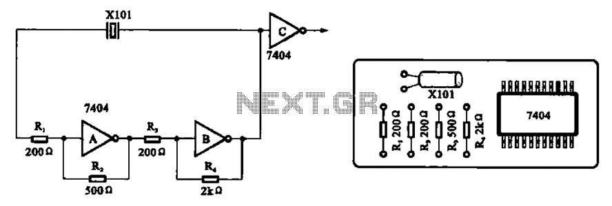
A clock oscillator is commonly utilized in digital signal processing circuits and microprocessor circuits. Digital signal transmission and signal processors necessitate a clock, which serves as the system's timing signal, while the data signal functions as a synchronization signal....
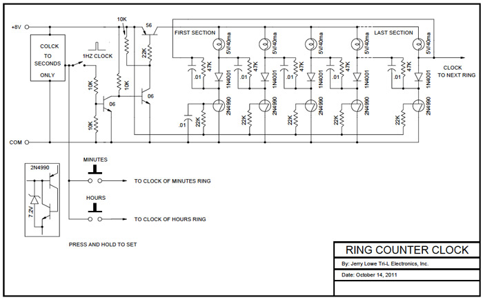
A Ring Counter Clock was designed and built in 1970. The base is a 12-inch diameter, 2-inch thick block of walnut sourced from a hollowed-out gun stock blank. The backside of the base has been hollowed out to accommodate...
This is a chronological account of a project to design and build a digital clock based on the Arduino open-source architecture, utilizing the ATMEGA8 microcontroller. The ATMEGA8 is an 8-bit, 16MHz microcontroller with integrated digital and analog inputs and...
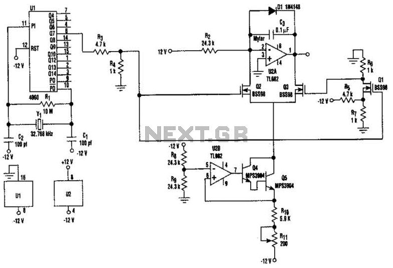
U2-a, U3, and R2 function as an integrator. Q2 and Q3 are alternately switched at 256 cycles. U2-b, Q4, Q5, and R8 through R11 form a constant current generator, with R11 configured to produce a symmetrical triangular waveform. The circuit...
Last year, I found a 31 day pendulum wall clock (disassembled) in a box of parts at a swap meet and decided to try and put it together and regulate it with a quartz crystal oscillator. The escapement part...
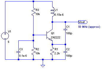
The core of any transmitter is typically an oscillator circuit, and in simple transmitters, such as QRSS devices, a crystal is often used. Frequency adjustment is achieved by modifying the capacitance to ground on one of the crystal's legs....