
Linear transformer signal conditioner
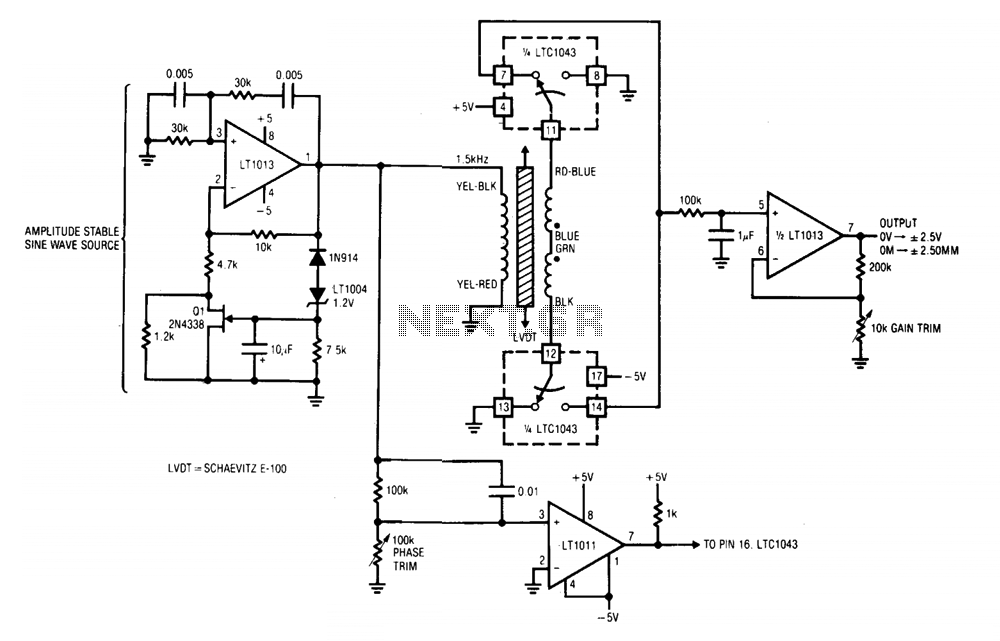
These outputs are summed at a low-pass filter that feeds into A2. A2 provides gain scaling and the circuit's output. The synchronized clocking of the LTC1043 ensures that the information presented to the low-pass filter is sensitive to both amplitude and phase. The circuit output indicates how far the core is from the center and on which side it is displaced. To calibrate this circuit, the LVDT core must be centered in the transformer, followed by adjusting the phase trim for a 0 V output. Subsequently, moving the core to either extreme position requires setting the gain trim for a 2.50 V output.
A comprehensive understanding of the circuit can be derived from its components and their interactions. The Wien bridge oscillator configuration in A1 is critical for generating a stable sine wave at the desired frequency of 1.5 kHz. The LT1004 reference is a precision voltage reference that enhances the stability of the oscillator, ensuring that variations in supply voltage do not affect the amplitude of the output sine wave. The unity-gain feedback loop is essential for maintaining the desired gain without introducing distortion, allowing the sine wave to drive the LVDT effectively.
The role of capacitor C1 is significant as it detects zero crossings, which are crucial for synchronizing the LTC1043 clock. The speed-up network is designed to counteract any phase shifts introduced by the LVDT, ensuring that the clock signal remains in sync with the transformer's output. This synchronization is vital for accurate rectification, as the LTC1043 alternates the connection of the transformer ends to ground, allowing for positive half-wave rectification. The resulting signal at pins 7 and 14 is then processed further.
The low-pass filter following the LTC1043 is designed to smooth out the rectified signal, presenting a clean output to A2. A2's function is to scale this signal appropriately, providing the necessary gain to reflect the position of the LVDT core accurately. The circuit's design ensures that the output is both amplitude and phase-sensitive, providing a reliable indication of the core's position relative to the center.
Calibration of the circuit is straightforward but critical for accurate operation. Centering the LVDT core ensures that the system operates from a known reference point. Adjusting the phase trim to achieve a 0 V output at the center position is essential for establishing the baseline. After this, moving the core to its extreme positions and setting the gain trim to 2.50 V output ensures that the system can accurately reflect the full range of motion of the core, providing a linear response throughout its operational range. This careful calibration process is key to achieving optimal performance from the circuit.A1 and its associated components furnish an amplitude stable sine wave source. All positive feedback path is a Wein bridge, tuned for 1.5 kHz, Ql, the LT1004 reference, and additional components in Al's negative loop unity-gain stabilize the amplifier. Al's output an amplitude stable sine wave, drives the LVDT. Cl detects zero crossings and feeds the LTC1043 clock pin. A speed-up network at Cl's input compensates LVDT phase shift, synchronizing the LTC1043's clock to the transformer's output zero crossings.
The LTC1043 alternately connects each end of the transformer to ground, resulting in positive half-wave rectification at pins 7 and 14. These points are summed at a low-pass filter which feeds A2. A2 furnishes gain scaling and the circuit's output. The LTC1043's synchronized clocking means the information presented to the low-pass filter is amplitude and phase sensitive. The circuit output indicates how far the core is from center and on which side. To calibrate this circuit, center the LVDT core in the transformer and adjust the phase irim for 0 V output.
Next, move the core to either extreme position and set the gain trim for 2.50 V output. 🔗 External reference
Related Circuits
10W HF linear amplifier circuit schematics free electronic circuits diagram wiring design plans schema DIY projects handbook guide tutorial schematic electronic schematic diagram project electronic schematic circuit diagram. The 10W HF linear amplifier circuit is designed to amplify high-frequency signals...
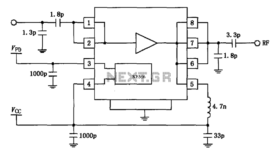
The circuit depicted in the figure is based on the RF2126, a 2450 MHz end-stage linear power amplifier. The radio frequency (RF) signal enters through input pin 1 and is subsequently amplified by the amplifier stages (pins 5, 6,...
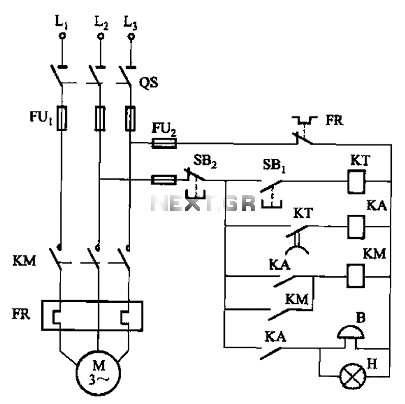
The circuit shown in Figure 3-21 is designed to produce a motor startup sound and a light signal indicating the completion of the startup process, after which the signal ceases. This circuit is tailored to control the motor for...
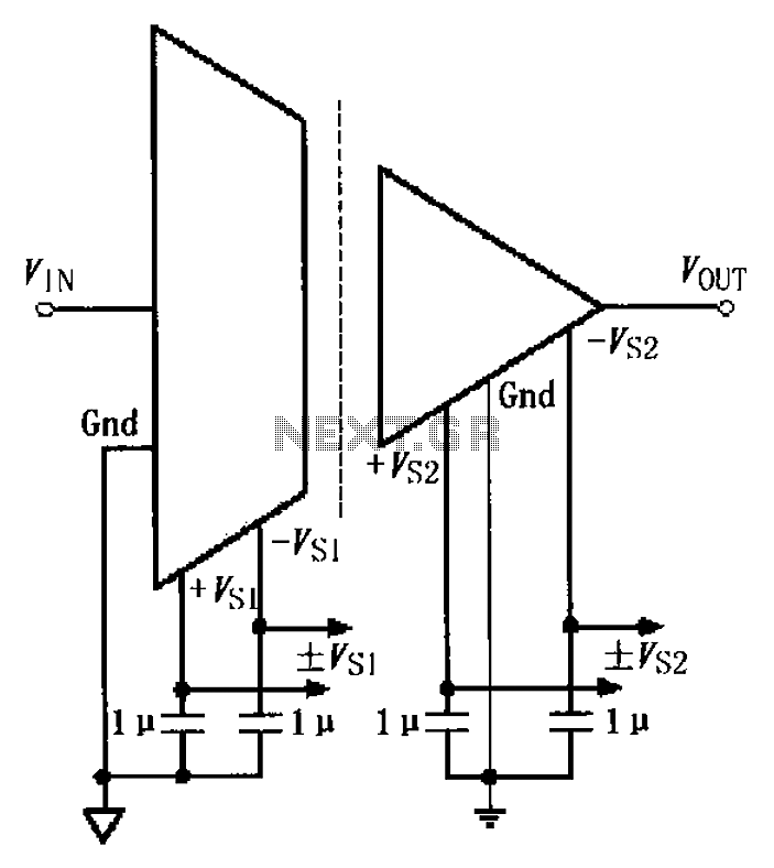
The basic connection circuit for the ISO122/124 includes power and signal connections. Each supply terminal of the ISO122/124 must be equipped with a 1 µF tantalum capacitor serving as a bypass filter. It is important to position the printed...
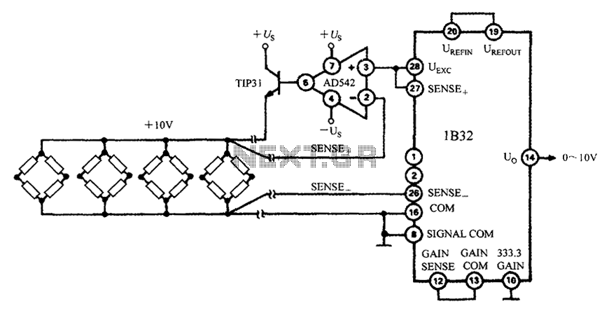
The 1B32 application circuit features multiple pressure sensors as illustrated in the figure. Excitation power is supplied through the AD542, which is followed by a TIP32 transistor that drives multiple bridge sensors. The AD542 operates as a Bi-FET in...
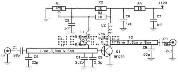
This amplifier is designed to amplify RF signals from an antenna by 10 dB and operates as a Class A amplifier using the BFQ34 transistor from Philips. The BFQ34 is packaged in an SOT122A case. The BFQ34T variant is...
Warning: include(partials/cookie-banner.php): Failed to open stream: Permission denied in /var/www/html/nextgr/view-circuit.php on line 713
Warning: include(): Failed opening 'partials/cookie-banner.php' for inclusion (include_path='.:/usr/share/php') in /var/www/html/nextgr/view-circuit.php on line 713