
One-IC two-tones Siren

The circuit is designed to generate two distinct audio tones that can be used for signaling purposes, such as in emergency vehicles. The primary component of this circuit is an integrated circuit that is capable of producing sound frequencies corresponding to the specified tones.
The two-tone police sound is typically characterized by alternating frequencies, creating a distinctive alert that is easily recognizable. In contrast, the single-tone ambulance sound provides a continuous tone that can be used in situations where a single alert is sufficient.
The resistors play a crucial role in determining the frequency of the oscillations produced by the circuit. Resistors R1 and R3, each rated at 470K ohms, are used in conjunction with R2, which is rated at 680K ohms, to set the timing intervals for the oscillation. The values of these resistors can be adjusted to modify the pitch and duration of the tones generated by the circuit, allowing for customization based on specific requirements.
In practical applications, this siren circuit can be powered by a standard DC power supply, and it may include additional components such as capacitors for filtering and smoothing the output signal. The output of the circuit can be connected to a speaker or a piezo buzzer to produce audible sound. Proper layout and connections in the circuit diagram are essential to ensure optimal performance and reliability of the siren tones.
Overall, this circuit serves as a versatile and effective solution for generating emergency alert sounds in various applications, including police cars, ambulances, and other emergency response vehicles.One-IC two-tones Siren. Double-tone Police sound. Single-tone old ambulance sound. Circuit diagram: Parts: R1,R3 470K 1/4W Resistors R2 680K 1/4W. 🔗 External reference
Related Circuits

The ramp voltage from the low-frequency oscillator IC1 modulates IC2, thereby producing a rising and falling tone similar to the wail of police cars. The described circuit utilizes a low-frequency oscillator (IC1) to generate a ramp voltage. This ramp voltage...
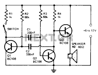
The circuit comprises a multivibrator (Q1 and Q2) and a low-power output stage (Q3). The speaker should have an impedance ranging from 40 to 80 ohms. To accommodate a low-impedance speaker, an output transformer should be connected from the...
This circuit provides a good siren noise suitable for warding off robot-predators! Change the pitch by adjusting R2, and R5. More: all resistors are 5 or 10 percent tolerance, 1/4-watt all capacitors are 10 percent tolerance, rated 35 volts...
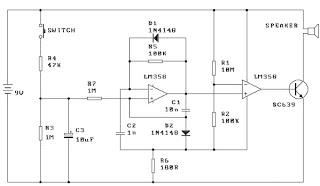
When the switch is pressed, capacitor C3 charges through resistor R4 with a time constant of 0.47 seconds. Upon releasing the switch, C3 discharges more slowly through resistors R7 and R3, with a time constant of approximately 5 seconds....
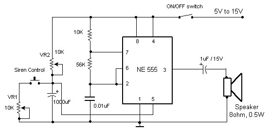
The circuit diagram of an electronic siren based on the NE555 timer produces a sound similar to that of a factory siren. The NE555 timer IC functions as an astable multivibrator with a center frequency of approximately 300 Hz....
This circuit is intended for children fun, and can be installed on bicycles, battery powered cars and motorcycles, but also on models and various games and toys. With SW1 positioned as shown in the circuit diagram, the typical dual-tone...