
one ic two tones siren
The circuit functions as a playful accessory that enhances the experience of riding or playing with various vehicles. It typically incorporates simple electronic components such as LEDs, sound modules, and possibly interactive sensors to engage children. The design may include a power supply circuit, often powered by batteries, to ensure portability and ease of installation.
The schematic likely features a microcontroller or timer IC that manages the operation of lights and sounds, allowing for various modes of operation such as flashing lights or sound effects triggered by movement or specific actions.
For installation, the circuit may include connectors for easy attachment to the vehicle's frame or body, ensuring a secure fit while allowing for easy removal when necessary. Additionally, protective casing may be included to shield the electronic components from environmental factors, such as moisture or dust, thereby enhancing durability.
Overall, this circuit serves not only as a source of entertainment but also promotes safety by making the vehicle more visible during low-light conditions, contributing to a fun and safe experience for children.This circuit is intended for children fun, and is suitable to be installed on bicycles, battery powered cars and motorcycles, but also in models and other games.. 🔗 External reference
Related Circuits
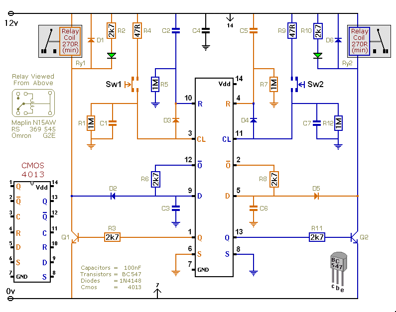
This versatile circuit offers a selection of different switching modes. It can function as two entirely separate toggle switches, with each push button successively energizing and de-energizing its corresponding relay. Alternatively, the two switches can be interconnected with diodes...
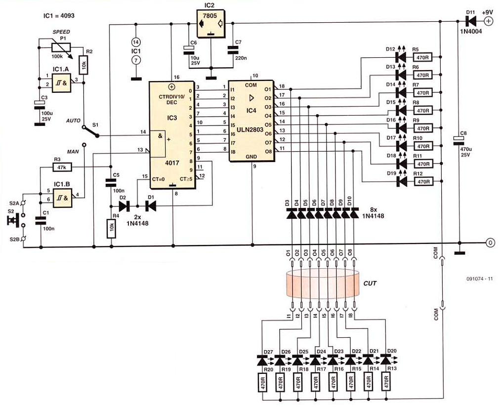
This network wiring tester consists of two components: a transmitter unit, which is powered and installed at the network's starting point, and a passive receiver unit that can be moved from socket to socket. Both units contain eight LEDs,...

The 3133 circuit is illustrated in Figure 3-133. It features dynamic braking controlled manually via buttons in three separate lines. In part (a) of the figure, the dynamic braking DC power supply is depicted with a step-down transformer and...

The ramp voltage from the low-frequency oscillator IC1 modulates IC2, thereby producing a rising and falling tone similar to the wail of police cars. The described circuit utilizes a low-frequency oscillator (IC1) to generate a ramp voltage. This ramp voltage...

A while ago I got an email asking for the schematic of a circuit to detect cut phone lines. It didn’t take me long to find this circuit in Electronics Now. When the circuit detects that a phone line...
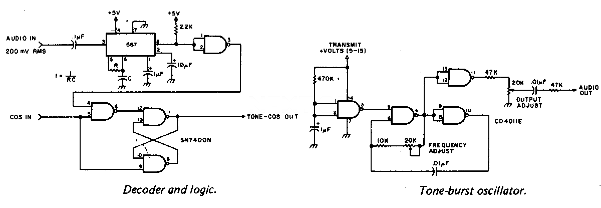
A tone burst sent at the beginning of each transmission is decoded at the receiver by a phase-locked loop (PLL), resulting in an output from pin 3 of a logic gate that activates a carrier-operated switch (COS). In this circuit,...