
One Of Nine Sequencer
The circuit design employs a 4017 decade counter, which is a CMOS integrated circuit capable of counting from 0 to 10, activating a corresponding output for each count. The clock input (CP0) is driven by a flashing LED, which serves as a simple yet effective timer. The frequency of the flashing LED determines the counting speed of the 4017, making it suitable for applications that require timed sequences.
Each output pin (Q0 to Q9) of the 4017 can be used to control various loads, such as lights or other electronic devices. The outputs are capable of sourcing a significant current, allowing for direct control of high-power devices. However, due to the limitations of the 4017 output current, the circuit incorporates a power transistor (such as the 2N3055E) to handle higher loads. The transistor acts as a switch, enabling the 4017 to control devices that require more power than the IC can provide directly.
The choice of resistor values between CP0 and ground is crucial for adjusting the brightness of the LED and, consequently, the clock frequency. A lower resistance will increase the current through the LED, resulting in a brighter flash and a more pronounced clock signal. Conversely, a higher resistance will dim the LED and decrease the clock frequency, thus slowing down the counting sequence.
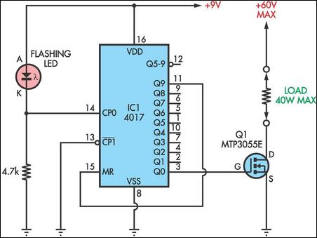
In applications such as Christmas light sequencing, this circuit can create captivating light displays by illuminating different strings of lights in a controlled manner. By connecting the outputs to different light strings and adjusting the MR pin, the sequence can be tailored to the user's preferences. Overall, this circuit exemplifies a practical and versatile approach to using a decade counter for timed output control in various electronic applications.This novel circuit uses a flashing LED as the clock input for a 4017 decade counter. Typical flashing LEDs (eg, DSE cat Z-4044) flash at about 2Hz so the outputs Q0-Q9 will cycle through at that rate. For example, Q0 will turn on for half a second, then Q1, then Q2 etc up to Q8 then it will start at Q0 again.
Up to nine outputs can be used. If you want fewer outputs, connect an earlier output to MR, pin 15. If MR is not used, connect it to 0V. Uses for the circuit include sequencing different strings of Christmas lights etc. The resistor from CP0 to ground can be anywhere from about 330O to about 10kO. Lower values will cause the LED to flash more brightly if that is required. With a 4. 7kO resistor as shown, the clock input CP0 (pin 14) will alternate between about 2V and 7V. To drive loads of up to 40W at up to 60V, connect each output to the gate of a 2N3055E or equivalent Mosfet (MTP3055E etc), as shown for Q0. 🔗 External reference
Related Circuits

Audio can be extracted from a telephone line using a transformer and a capacitor to isolate the line from external equipment. A non-polarized capacitor is placed in series with the transformer line connection to prevent direct current from flowing...
A DIY GSM jammer schematic diagram designed for use with GSM1900, operating within the frequency range of 1930 MHz to 1990 MHz. The GSM jammer circuit is intended to disrupt communication between mobile phones and base stations within the specified...
Here is a teleremote circuit which enables switching on and off of appliances through telephone lines. It can be used to switch appliances from any distance, overcoming the limited range of infrared and radio remote controls. The circuit described...
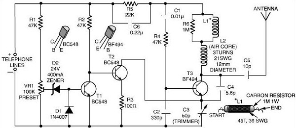
This schematic outlines a simple FM transmitter designed to operate using a phone line for both power and audio signal reception. By connecting the device to the desired phone line, it enables monitoring of conversations. Users can tune their...
The following circuit illustrates a Bass and Treble Controller Circuit. This circuit is constructed based on the classic Baxandall tone control circuitry. The Bass and Treble Controller Circuit is designed to adjust the low and high-frequency response of audio signals,...
When power is applied, the 15K resistor and 10µF capacitor at pin 15 will reset the counters to a zero count, with pin 3 at +12V and all other outputs at zero. The two diodes (1N914) and a 15Ω...