
One transistor LED Flasher
The LED flasher circuit described operates on a simple principle of charging and discharging a capacitor through a transistor. The 2N2222 NPN transistor is used in this circuit with its base lead removed, allowing for a direct connection between the emitter and collector. This configuration exploits the transistor's ability to switch on and off based on the voltage across the capacitor, which is charged through a 1kΩ resistor.
Initially, the 330 µF capacitor charges until the voltage reaches approximately 9 volts. At this threshold, the emitter-base junction of the transistor enters avalanche breakdown, causing the transistor to turn on rapidly. This results in the capacitor discharging through the LED and the 100 Ω current-limiting resistor, producing a flash of light. The current flowing through the circuit peaks at around 26 mA, as indicated by the oscilloscope measurements. Once the discharge current drops to 6 mA, the transistor turns off, halting the conduction and allowing the capacitor to recharge, thereby initiating a new cycle.
The choice of charging resistor is critical for the operation of the circuit. If the resistance is too low, the capacitor will charge too quickly, preventing the transistor from turning off. Conversely, if the resistance is too high, the capacitor may not charge sufficiently to turn the transistor on. The circuit can accommodate various LED types, including those with integrated resistors, but caution should be exercised regarding the peak current to avoid damaging the LED.
The oscillation frequency of the circuit can be adjusted by varying the capacitor's value; a smaller capacitor will yield faster oscillation and shorter flash durations. The 2N2222 transistor is noted for its reliability in this application, although other transistor types may exhibit unpredictable behavior. This LED flasher circuit represents a practical and simple approach to creating flashing LED effects, suitable for various applications.This may be the simplest LED flasher circuit you can build, with the notable exclusion of LED's with integrated flashing circuits. This might be a good replacement for the LM3909 in some applications. Take a close look. Only the emitter and collector leads of the 2N2222 are connected. The base lead was cut off. The LED is from a string of Christmas lights and it has an integrated 100 Ohm resistor. This LED flasher occurred to me while reading about negative resistance in transistors. In this implementation, a common NPN transistor is used. In the circuit, a 1k resistor charged the 330 uf capacitor until the voltage became large enough to get the emitter-base junction to avelanche.
If the resistor that charges the capacitor is too low in value (or if the power supply voltage is too high), the current through the transistor will not become low enough for the transistor to turn off. If the resistor that charges the capacitor is too high in value (or the power supply voltage is too low), the capacitor will not be able to charge to a high enough voltage to enable the transistor to turn on.
This is because the transistor draws as small amount of current before switching on. In the oscilloscope image, it can be seen that the peak voltage (yellow trace) was a little bit less than 9 volts. At this point transistor turned on quickly and partially discharged the 330 uf capacitor through the LED and the 100 Ohm current limiting resistor.
The current wavform, which is the voltage drop across the 100 Ohm resistor, is shown in the blue trace on the scope image. Peak current was 26 milliamps, and the transistor continued to discharge the capacitor until conduction suddenly ceased at 6 milliamps (Many thanks to Luke in Australia for pointing out the correct current).
After the transistor stopped conducting, the capacitor began charging again, thus starting a new cycle. I've tried this with red LED's with and without integrated current limiting resistors, and on some while LED's.
This circuit can be built without the current limiting resistor, but if you choose to do so, please be aware that the peak currents may be high enough to shorten the life of the LED. The capacitor value isn't critical. A lower value will result in faster oscillation and shorter flashes. The 2N2222 NPN transistor seems to work reliably in this circuit. Other transistors may be more tempermental, and others might not work at all. 🔗 External reference
Related Circuits
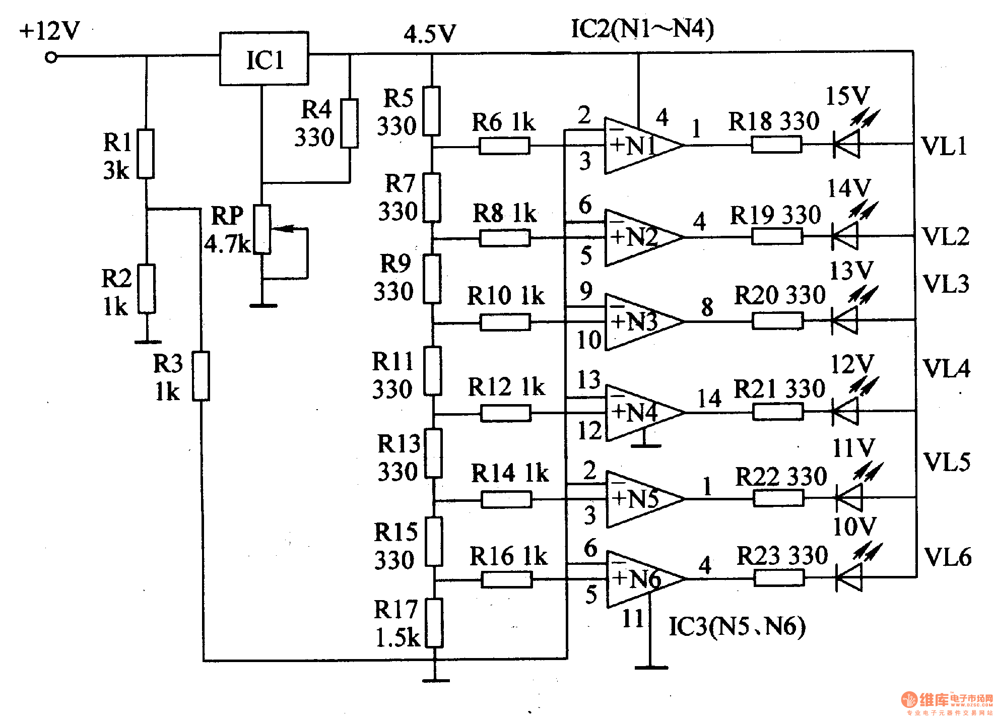
This document introduces an LED car voltmeter constructed using the op-amp LM312 and LED components. It is designed to display six voltage levels ranging from 10V to 15V, with each level representing a 1V increment. The working principle of...
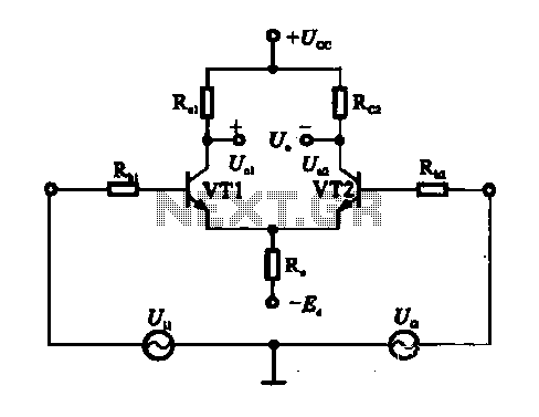
An emitter-coupled differential amplifier circuit is designed to suppress zero drift through circuit symmetry. The effectiveness of zero drift suppression improves with better symmetry; however, in practice, achieving complete symmetry is not feasible. Consequently, the basic differential amplifier circuit...

The circuit utilizes two unijunction transistors. The low-frequency sawtooth generated by Q1 modulates the high-frequency tone produced by Q2. The output is designed to feed into a high-impedance amplifier. Both Q1 and Q2 are 2N4871 transistors. The circuit comprises two...
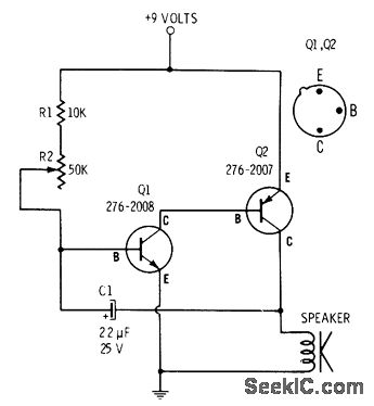
R2 controls the charging speed of capacitor C1. At a specific charge level, C1 triggers transistors Q1 and Q2, which release a 9-volt pulse. This pulse generates a clicking sound. The discharge process of the capacitor involves it charging...
The Metal-Oxide-Semiconductor Field-Effect Transistor (MOSFET) is analogous to the Junction Field-Effect Transistor (JFET) in several aspects. Both types are voltage-driven unipolar devices that rely on either electron or hole movement, but not both, unlike bipolar transistors. A key structural...
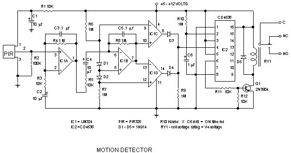
Detector components and infrared motion work, electronic circuit schematic wiring diagram, detector components and infrared motion work. The electronic circuit schematic for an infrared motion detector typically consists of several key components that work together to detect motion through infrared...
Warning: include(partials/cookie-banner.php): Failed to open stream: Permission denied in /var/www/html/nextgr/view-circuit.php on line 713
Warning: include(): Failed opening 'partials/cookie-banner.php' for inclusion (include_path='.:/usr/share/php') in /var/www/html/nextgr/view-circuit.php on line 713