
one tube regen radio circuit
The regenerative radio circuit is a classic example of early radio technology, leveraging feedback to enhance signal reception. The Audion tube serves as the heart of the circuit, functioning both as the detector and amplifier, which allows for the amplification of weak radio signals. The design's simplicity makes it accessible for hobbyists and electronics enthusiasts.
The construction of the coils (L1, L2, and L3) is critical for the performance of the radio. The use of a toilet paper tube as a coil form is a practical and cost-effective choice, with the 26 AWG wire providing sufficient inductance. The precise winding of the coils is essential; overlapping turns can lead to inefficient coil performance and reduced sensitivity. The tap on L3 is particularly important as it allows for feedback to be fed back into the circuit.
The combination of R1 and S1 into a single unit is a thoughtful design choice. It not only simplifies the circuit layout but also enhances user safety by preventing accidental full regeneration, which could damage the headphones or create an unpleasant experience. The selection of antennas is also crucial; while a short indoor antenna may suffice for testing, a longer outdoor antenna significantly improves reception quality, allowing for clearer and more stable sound.
Overall, this regenerative radio project encapsulates the fundamental principles of radio technology, including signal amplification, feedback mechanisms, and tuning, making it an excellent educational tool for understanding the basics of radio electronics.A regenerative radio works by feeding back a small amount of amplified output of the detector back into the input. Thus it achieves sensitivity far beyond what only a detector could alone. This simple regen radio uses a single tube as it`s detector and amplifier; the "Audion". It`s a great first project for those wishing to bring back some nostalg ia by building one of the first amplified radio sets. Built on a board using point to point wiring and a set of period headphones, it can be a great functional conversation piece. L1 - L3 are constructed on the same coil form. A toilet paper tube will be the coil form. Secure the 26 AWG wire to the form by punching two holes close together and winding the wire once around the "bridge" between them.
Alternately, just a drop of hot glue can be used. Leave about 6" of wire. Wind on twenty turns close together but never overlapping. Make a tap by securing the wire with a drop of glue and twisting a loop. This is L3. Wind 80 more turns in the same direction and then secure the end, leaving about 6" of wire at the end. This is L2. Now secure the 26 AWG wire 1/8" from the end of L2 and wind 30 turns in the same direction as the other coils, making sure that this coil is spaced 1/8" evenly from L2.
Secure the end and leave about 6" lead. This is coil L1. Now trim the extra length of the coil form and spray the coil with several coats of lacquer to hold the wires in place. R1 and S1 can be one unit if you purchase a pot with a built in switch. This will avoid turning the set on with full regen and causing a nasty squeal from the headphones. An antenna of only a few feet can be used for ANT1 for easy indoor installation. Far better is an antenna of 50 feet or more outside, which would be connected to ANT2. To use the set, place C2 at about midway, set R1 fully counterclockwise and then turn on S1 and allow the tubes several seconds to warm up.
Increase R1 until the headphones squeal, then back off. That is when the set is most sensitive. Now tune C2 to the desired frequency. You may have to readjust R1 as you tune different frequencies. With some practice you will figure out how much regen you need as you change stations. 🔗 External reference
Related Circuits
The phone company provides 3 levels of power. With no devices 'off hook' the line rests at 48 volts DC. If you draw any more than a fraction of a milliamp or so, you get the phone company's attention...
This is a simple power resumption alarm circuit that can be installed within the switch box. It emits beeping sounds when power is restored following a power outage. The power resumption alarm circuit serves as a practical solution for alerting...
The following circuit illustrates a Mains Remote-Alert Circuit Diagram. Features include simple circuitry, with the transmitted signal being conveyed effectively. The Mains Remote-Alert Circuit is designed to provide a notification system that alerts users about the status of mains power....
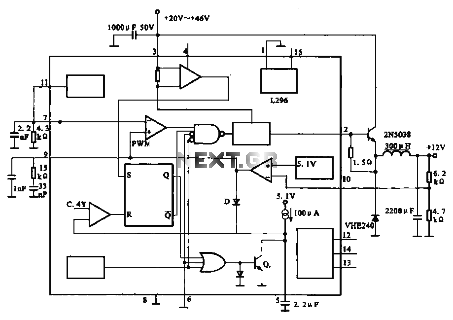
The circuit outputs 12V at 10A and utilizes a high-current switching power supply design based on the L296 component. This configuration allows for an output current of up to 10A, and the entire circuit is compact with minimal component...
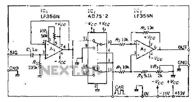
An analog switch (double loop, double-break) and a differential modulation amplifier are used in this circuit. The carrier control switch operates by switching contacts at specific times, inverting the input modulation wave. When the next carrier signal is applied...
The AM signal is captured by the antenna, 10 mt long horizontal wire, WELL insulated from earth. The inductor and capacitor form a resonator, that will tune with the station whose frequency is F = 1 / (2 *...