
Op Amp Wien-Bridge Oscillator
CIRCUIT ANALYSIS involves running a SPICE simulation of the open-loop circuit (OPWEIN_OL.CIR) and adding a trace for VM(3) to observe the magnitude at the center frequency. With R1 = R2 = 10kΩ and C1 = C2 = 16nF, the center frequency should approximate 1 kHz. An additional plot window can be created to add trace VP(3) to observe the phase shift. The RC network effectively meets one oscillation condition by achieving a 0-degree phase shift at the design frequency; however, it falls short as the gain is only 1/3 V/V. To achieve a gain of 1 V/V, a non-inverting amplifier is utilized, providing a gain of 3 V/V, resulting in a total gain of 1/3 x 3 = 1 V/V. Setting the appropriate op-amp gain is vital; insufficient gain will halt oscillations, while excessive gain will cause saturation. A mechanism is required to ensure oscillations commence (GAIN > 3) and to limit gain at steady state (GAIN = 3). Diodes D1, D2, and resistor R12 facilitate this adjustment. For small signals, the diodes do not conduct, and gain is set accordingly. For larger signals, the voltage across R12 activates the diodes, reducing their shunt resistance and thereby lowering the overall gain to GAIN = 3.
CIRCUIT ANALYSIS continues with a simulation of OPWIEN_OL.CIR, where the AC output of the op-amp (VM(4)) is observed. For R10 = 10kΩ, R11 = 18kΩ, and R12 = 5kΩ, the op-amp gain calculates to (1 + (18 + 5)/10) = 3.3 V/V. This results in an overall open-loop gain of 1/3 x 3.3 = 1.1 V/V. The peak at VM(4) should reach this expected gain. Closing the loop involves simulating the closed-loop circuit (OPWIEN.CIR) and plotting the transient analysis at V(4) to determine the stabilization time of the amplitude.
HANDS-ON DESIGN encourages experimenting with different oscillation frequencies. To calculate new values for R and C, for instance, if the desired frequency (fo) is 10 kHz, R1 = R2 = 10kΩ can be selected, and C1 = C2 can be calculated using the formula C = 1/(2 x R1 x fo), yielding C = 1.6nF. Testing the oscillator may require adjusting the total time of the transient analysis to accommodate the desired output, such as modifying the TRAN statement to extend to 5 ms.The opamp Wien-bridge oscillator provides a nice view into classic oscillator design using feedback analysis. Feedback analysis reveals if your circuit is stable (well behaved) or unstable (may oscillate). When designing amplifiers (especially high-speed ones), the trick is to avoid the conditions that make the circuit oscillate.
When designing os cillators, you strive to achieve those conditions in a predictable way. Feedback analysis simply means opening the circuit and injecting an AC signal VTEST at one end of the circuit. Then, by looking at the magnitude (gain) and phase (time-shift) of signal as it travels around the opened loop, you can tell whether you`ve got an amplifier or an oscillator on your hands.
When wearing your oscillator design hat, the idea is to pick components that will make the open-loop analysis meet the conditions for oscillation at your chosen frequency: The conditions are as follows: Open the loop of the Wien Bridge Oscillator at the op amp`s output. This is a good point because of the relatively low impedance of the output terminal. Likewise, VTEST also has a low output impedance. Therefore, opening the loop here does not significantly alter the circuit`s behavior. Two basic sections form the Wien-bridge oscillator: an RC tuning network and an amplifier. Both are necessary to achieve the conditions for oscillations. The RC network is characterized by a center frequency where R=R1=R2 and C=C1=C2. At the center frequency, two interesting things occur at V(3). First, the phase shift goes through 0 degrees. And second, the magnitude reaches a peak of 1/3 V/V. CIRCUIT ANALYSIS Run a SPICE simulation of the open-loop circuit OPWEIN_OL. CIR. Add trace VM(3) to see what the Magnitude looks like at the center frequency. For R1=R2=10k and C1=C2=16nF, the center frequency should be near 1 kHz. What does the phase look like Add another plot window and then add trace VP(3) to see the Phase shift.
The RC network does a nice job of meeting one of the conditions for oscillation: the phase is 0 degrees at the design frequency. The RC network falls short of the oscillation conditions in that the gain is only 1/3 V/V. How is the gain of 1V/V around the loop to be achieved As you might have guessed, the non-inverting amplifier provides the needed gain.
How much A gain of 3 V/V makes the total gain 1/3 x 3 = 1 V/V. Setting the correct op amp gain is critical. Not enough - oscillations will cease. Too much oscillation amplitude will grow until the output saturates. What`s needed is a mechanism to guarantee oscillations will start (GAIN > 3), yet, limit the gain (GAIN=3) at steady state. Enter our heros - D1, D2 and R12. The circuit adjusts its gain depending on the signal level. For small signals, the diodes do not conduct and the gain is set by For larger signals, the voltage across R12 is big enough to make D1 and D2 conduct.
The shunt resistance of the conducting diodes effectively reduces the R12 resistance, consequently, reducing the overall gain to GAIN=3. CIRCUIT ANALYSIS Run a simulation of OPWIEN_OL. CIR. View the AC output of the op amp VM(4). For R10=10k, R11=18k and R12=5k, the op amp gain is (1 + (18+5)/10) = 3. 3 V/V. This should make the overall open-loop gain equal to 1/3 x 3. 3 = 1. 1 V/V. Does the peak at VM(4) reach this expected gain It`s time to close the loop and try out the Wien-Bridge Oscillator.
Run a simulation of closed-loop circuit OPWIEN. CIR and plot the Transient Analysis at V(4). How much time does it take for the amplitude to stabilize HANDS-ON DESIGN Design the circuit with a different oscillation frequency. Calculate the values for R and C. (Example: For fo = 10kHz, choose R1=R2=10k and calculate C1=C2=1/(2 x R1 x fo) = 1. 6nF. ) Test drive your oscillator. If there`s too little or too many sinewaves on the plot, adjust the total time of the Transient Analysis to another value like 5 ms by modifying the.
TRAN statement to l 🔗 External reference
Related Circuits
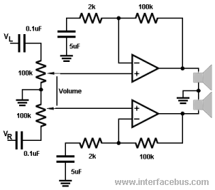
The 100k potentiometers adjust the voltage levels reaching the operational amplifiers (Op Amps). A dual ganged 100K-Ohm audio-taper potentiometer is preferred over a linear taper potentiometer. In some instances, this component may be referred to as a ganged stereo...
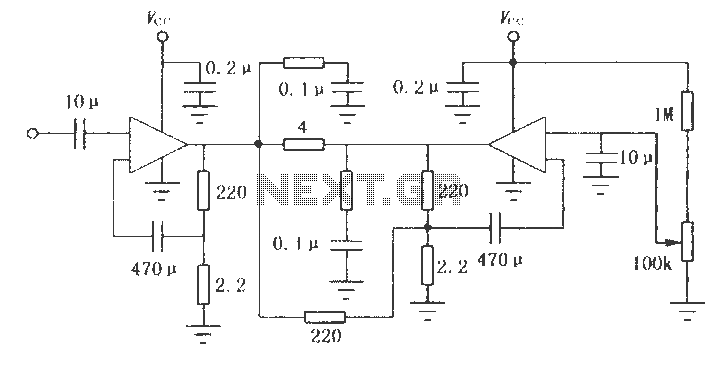
One still designing that it uses in the exit transistor of technology V-mosfet. This transistors to us offer a lot of virtues concerning the simple bipolar transistors, as high speeds, thermic stability, low distortion etc. Beyond this circuit use...
The LM2002 / 2002A is an audio power amplifier integrated circuit. The LM2002A features high voltage protection, with a maximum instantaneous power supply voltage of up to 40V, and comes in a 5-pin single in-line plastic package. This integrated...
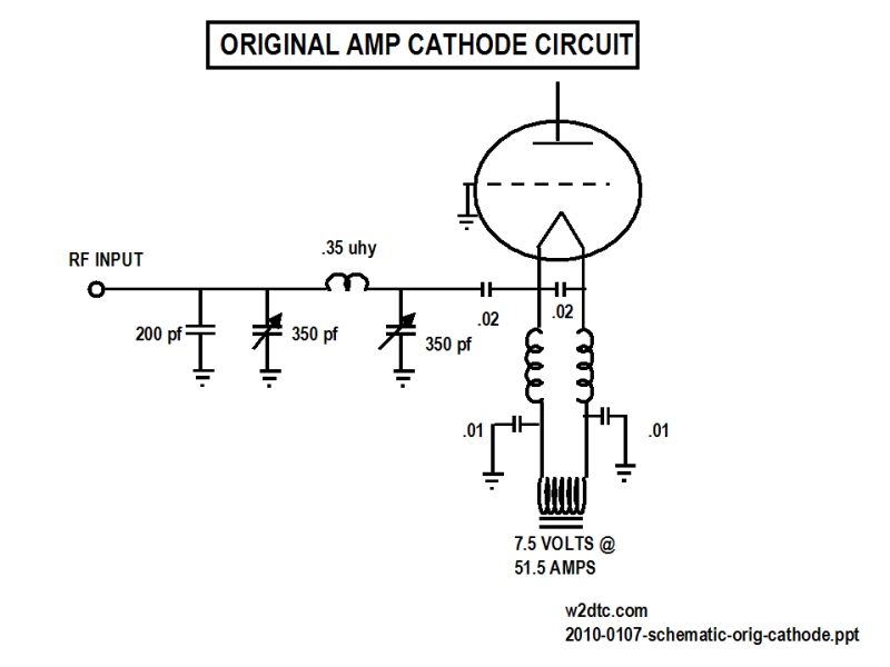
Conversion of a 3CX3000F7 plasma amplifier for use on the 40-meter band, including photographs and detailed descriptions. The 3CX3000F7 is a high-power vacuum tube typically used in RF amplification applications. Converting this amplifier for operation on the 40-meter band involves...
I am attempting to construct a Hartley oscillator using a bypassed common emitter configuration. The goal is to achieve oscillation at a frequency of 200 kHz with a peak-to-peak voltage of 2 V, utilizing a BC547B transistor. The Hartley oscillator...
Q1 and Q2 create an ALL-ON ALL-OFF circuit that, when in the off state, draws negligible current. P1 initiates the circuit, activating the relay and powering the two integrated circuits (ICs). The lamp is energized through the relay switch,...