
Opamp Wien-bridge oscillator
The Wien-bridge oscillator is a type of electronic oscillator that generates sine waves. It employs a specific arrangement of resistors and capacitors to establish the frequency of oscillation. The core of the circuit is an operational amplifier configured in a non-inverting mode, which provides the necessary amplification for the oscillations to sustain.
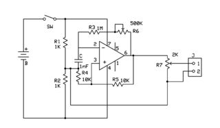
In the basic configuration, the Wien-bridge oscillator includes two resistors (R1 and R2) and two capacitors (C1 and C2) arranged in a bridge circuit. The resistors and capacitors are selected such that they set the frequency of oscillation according to the formula:
\[ f = \frac{1}{2\pi R \sqrt{C1 \cdot C2}} \]
where R is the resistance value chosen for R1 and R2. The gain of the operational amplifier is determined by the ratio of R2 to R1, which must be greater than three for stable oscillation. This gain condition ensures that the feedback network provides the right amount of positive feedback to sustain oscillations.
To maintain stable oscillations and prevent saturation of the operational amplifier, a light bulb or thermistor is often used as a variable resistor in the feedback loop. This component adjusts the gain dynamically, allowing the oscillator to stabilize at the desired amplitude.
The output of the Wien-bridge oscillator is a sine wave, which can be utilized in various applications, including signal generators, audio applications, and testing equipment. The design's simplicity and effectiveness make it a popular choice in both educational and professional settings for generating high-quality sine waves.The Wien-bridge oscillator, consists of an Operational Amplifier (OA) in a non-inverting configuration with gain 1 + R2/R1 and a RC feedback network.. 🔗 External reference
Related Circuits
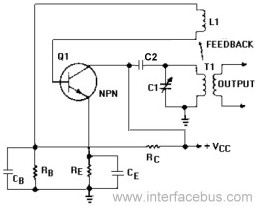
An Armstrong Oscillator is a type of oscillator that utilizes a tickler coil to provide feedback from the tank circuit. This oscillator generates a sine-wave output with constant amplitude and fairly constant frequency within the RF range. Inductor L1...
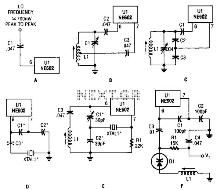
Any standard oscillator, such as a Colpitts or Hartley configuration, can be utilized to generate the local oscillator (LO) frequency required by the NE602. The NE602 is a versatile integrated circuit commonly used in radio frequency applications, particularly in mixer...
An attempt has been made to follow an instructable for some time; however, understanding its schematic remains challenging. The issue is not a lack of knowledge regarding the symbols used. In electronic schematics, symbols represent various components and their connections...
Here is a simple triangle/squarewave generator using a common 1458 dual op-amp that can be used from very low frequencies to about 10 Khz. The time interval for one half cycle is about R*C and the outputs will supply...
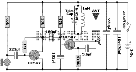
The following schematic diagram shows the design of a 100 MHz Radio Frequency RF Oscillator Circuit. The electrets microphone picks up and amplifies sound then fed it into the audio amplifier stage built around the first transistor. The output...
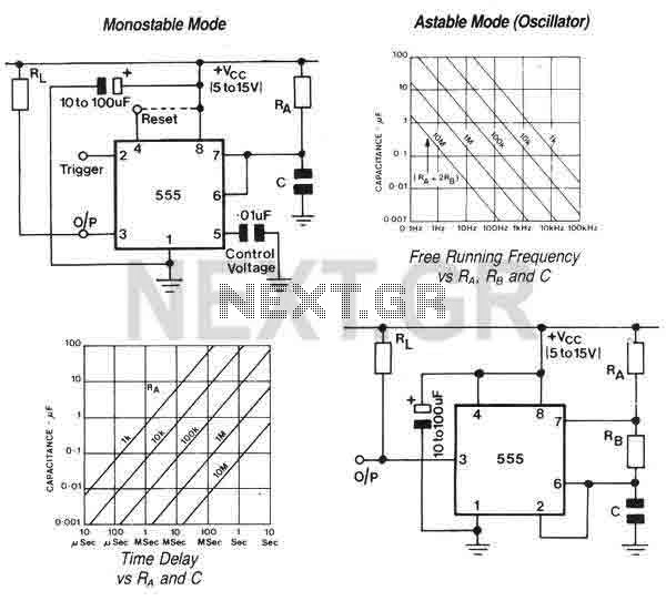
The 555 is a highly stable device for generating accurate time delays or oscillation. Additional terminals are provided for triggering or resetting if desired. In the time delay (monostable) mode of operation, the time is precisely controlled by one...