
Open water notification Circuit Design
For the production and testing method, two discarded fluorescent starter shells are utilized, secured with iron clamps and screws. One starter is positioned in the kettle's spout to measure water temperature. The thermistor's two pins are soldered onto the other starter cover and encapsulated within the shell, ensuring the thermistor is close to the shell wall for accurate heating. After verifying all components and connections, the system can be powered on for debugging. The temperature sensor is placed in the kettle's spout, and adjustments to the variable resistor (RP) are made until the water boils, at which point the piezoelectric ceramic emits sound. This testing may be repeated multiple times before the device is officially used. The sound frequency can be altered by changing the capacitance of C2, and if a louder sound is desired, transistors can be added to amplify the output from IC-4.
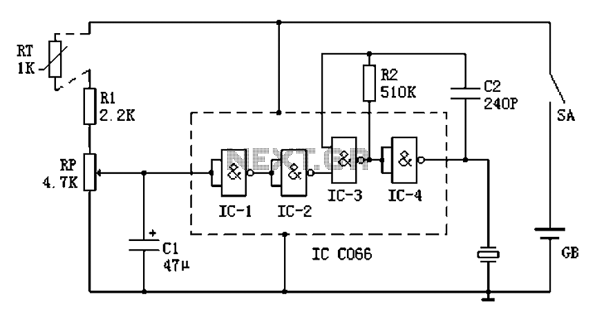
The circuit design effectively combines temperature sensing and sound notification to ensure safe boiling of water, preventing potential hazards associated with unattended boiling. The use of common electronic components simplifies the assembly and makes the system cost-effective while providing a reliable solution for monitoring boiling water. Boil water on the kitchen gas stove, once the water is boiling, if not stalled, spilling boiling water will come out, the flame extinguished. Gas spills, very safe. Water can s olve this problem after opening notification device. Circuit works : The circuit uses a thermistor as the temperature sensing element, when the water temperature rises, the thermistor resistance decreases, A point potential increases, when the A point potential is higher than the IC-1 inverters convert voltage, IC-1 will output low, IC-2 output high. So that IC-3, IC-4 audio oscillator work composed, piezoelectric ceramics sound. When IC-2 output low, IC-3, IC-4 consisting of audio oscillator is not working, piezoelectric ceramics silent.
IC selects C066 two-input NAND gate four, working voltage 3V ~ 18V, the power supply circuit is 3V ~ 6V; RT thermistor resistance is about selected 1k ; piezoelectric ceramics selected diameter of 27mm; use an ordinary resistor 1/8 or 1/4W metal film resistors. Production and Testing Method : find two waste fluorescent starter shell, made with iron clamps, snapping the top two starters and secured with screws.
Wherein a starter can be set in the mouth of the kettle to get water temperature. Thermistor two pins welded on the other starter cover and filled shell, attention must be close to the thermistor within the shell wall, it is easy to heat. Welding on the outer lead thermistor temperature sensors on the well. After all the components check and correct weld can turn on debugging, the temperature sensor set in the kettle mouth, adjusting RP and other water boils, the piezoelectric ceramic sheet just sound, several times repeated testing, it can officially use.
To change the sound frequency can vary the capacity C2. If you feel that the sound is not enough, you can add transistors in the output of IC-4, amplification sound effects.
Related Circuits
This power supply was designed for use with the Simple hybrid amplifier published elsewhere in this issue. It is suitable for various applications as well. A cascade generator is utilized for the 170 V output, a switch-mode supply provides...

The circuit described is a crystal oscillation circuit using a CM OS inverting configuration, designed to ensure accurate operation. It employs a BCD counter (IC2) capable of achieving a maximum oscillation frequency of 2 MHz, which is 100 times...
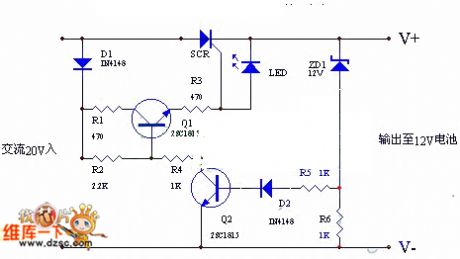
The circuit utilizes the positive half-cycle of an alternating current (AC) to charge a battery. It offers a rapid charging speed and has the potential to extend battery life. This charger is commonly used with standard motorcycles, demonstrating excellent...

The circuit is illustrated. A motor utilizes series resistance in the rotor winding for starting. The drawing includes electrical velocity off the relay KIi ~ KI3 for motor short circuit protection and overcurrent. Additionally, relays 1KI and 2KI provide...

A simple, high-efficiency switching power supply circuit can be designed using the LMZ13608 8A regulator. This regulator offers very high efficiency and requires few external components. It supports a wide input voltage range of 6 to 36 volts and...

This pulse generator produces square pulses ranging from 1Hz to 100KHz with an adjustable pulse width of nearly 0-100%. It operates on a voltage of 5-15V, making it suitable for both TTL and CMOS circuits. This device is essential...