
Radar signal detector
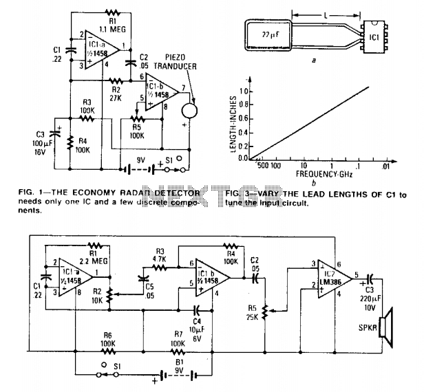
The described circuit is designed to operate effectively across a broad frequency range, specifically from 50 MHz to 500 GHz. This versatility makes it suitable for various applications, including radar signal processing and communication systems. The economy model and deluxe model configurations differ primarily in their output amplification stages, with the economy model utilizing a simple buffer to drive a piezo buzzer, while the deluxe model employs an LM386 amplifier for enhanced audio output.
In the economy model, the first operational amplifier serves as a current-to-voltage converter, transforming the incoming radar signal into a usable voltage level. This signal is then buffered by IC1b, ensuring that the piezo buzzer receives a stable and sufficient signal for operation. The design of the circuit allows for straightforward integration into systems requiring basic signal detection and audio output.
Conversely, the deluxe model enhances this functionality by incorporating a 20x buffer amplifier configuration. This setup allows for greater amplification of the signal, enabling the LM386 to drive more demanding loads, such as speakers or larger audio devices. The choice of the LM386 amplifier is particularly suitable due to its low power consumption and ability to deliver significant output power, making it ideal for portable or battery-operated devices.
Both models utilize capacitor C1 as a critical component in the transmission of the radar signal. This capacitor acts as a transmission line, capturing the incoming signal and facilitating its processing by the operational amplifiers. The performance of the circuit can be fine-tuned by adjusting the lead length of C1, which affects the impedance and, consequently, the frequency response of the circuit. The recommended lead length of 0.5 to 0.6 inches is a standard practice that helps optimize the circuit's performance at the desired frequency range.
Overall, the circuit's design is a practical solution for applications requiring radar signal detection and audio output, with flexibility for optimization based on specific requirements.The circuit can be tuned to respond to signals between 50 MHz and 500 GHz. The economy model is shown in Fig. 1, and the deluxe model is shown in Fig. 2.The first op amp in each circuit functions as a current-to-voltage converter. In the economy model IClb buffers the output to drive the piezo buzzer. The deluxe model functions in a similar manner except that IClb is configured as a 20 buffer amplifier to drive the LM386. In both circuits Cl functions as a "transmission line" that intercepts the incident radar signal. The response may be optimized by trimming Cl's lead length for the desired frequency. Typically the capacitor's leads should be 0.5-0.6 inches long. 🔗 External reference
Related Circuits
The OpenRelief project is developing open, modular information solutions for disaster relief, which includes a range of network-enabled sensors. A radiation detector prototype has been created using an ionization chamber instead of a Geiger-Muller tube, constructed from an old...
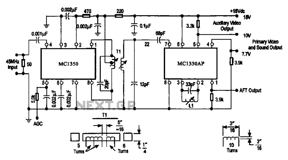
The circuit features an IF processing section utilizing the MC1350 and a video detector, the MC1330AP, which are integrated to form a combined video processing system. The modulation of the circuit is dependent on the image signal, with the...
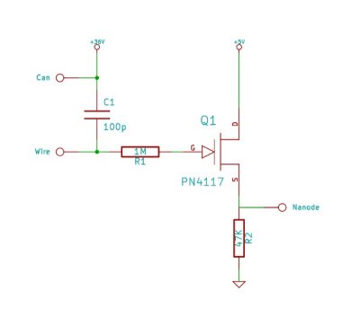
This simple circuit can detect the invisible fields of voltage which surround all electrified objects. It acts as an electronic "electroscope." Regular foil-leaf electroscopes deal with electrostatic potentials in the range of many hundreds or thousands of volts. The...
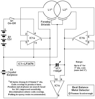
This is a metal detector circuit where the frequencies of two oscillators are mixed in a manner similar to a Beat Frequency Oscillator (BFO) to produce an audible heterodyne signal. At first glance, this design may appear to be...
This circuit is designed to trigger on a 1 kHz tone. To change this frequency, refer to the table below, then change the resistor and capacitor values accordingly. More: all resistors are 5 or 10 percent tolerance, 1/4-watt; all...
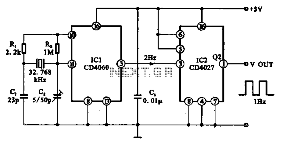
A 1Hz clock signal generator circuit is presented, which demonstrates a sophisticated clock signal generating mechanism. This circuit can be utilized for digital clocks and timing applications. It comprises a binary counter (CD4060), a JK flip-flop (CD4027), and a...