
Optimized 10-element UHF Yagi Antenna
The antenna design described involves a dipole configuration where the diameters of the elements are specified to ensure optimal performance. The elements can range from 5 mm to 8 mm in diameter, while the dipole itself has a recommended diameter of 12 mm, with a permissible range of 8 mm to 12 mm. This flexibility allows for variations in manufacturing and material choice without necessitating adjustments to the overall length or spacing of the antenna elements.
The boom, which serves as the central support structure for the antenna, has a diameter that can vary between 10 mm and 15 mm. The choice of boom diameter can affect the structural integrity and mounting options of the antenna. It is noted that all elements, apart from the dipole, should be electrically connected to the boom, which is crucial for maintaining the desired electrical characteristics of the antenna.
Mounting options are versatile, as elements can be affixed either on top of the boom or through it, depending on the design preferences and mechanical constraints. The use of an isolator type boom is recommended for vertical installations. Materials such as plastic tubing, wood, or fiberglass are suggested to minimize the impact on the antenna's performance due to their non-conductive properties.
The bazooka tube specifications indicate two options with diameters of 15 cm, where one variant has a wall thickness of 10 mm suitable for specific applications like Aircel, while the other has a thicker wall of 15 mm recommended for use with H100 and Aircom+ systems. These specifications are important for maintaining the structural and performance characteristics of the antenna system.
Overall, this antenna configuration provides flexibility in design and materials while ensuring that performance is not compromised. Proper attention to the diameter of elements and the boom, along with appropriate mounting techniques, will result in an effective antenna system suitable for various applications.The elements diameter of the antenna may vary between 5...8mm and the dipole diameter may vary between 8...12mm (12mm recommended) without the need of changing anything to the length or spacing. All elements except the dipole are electrically connected to the boom and may be mounted on top or through it.
The thickness/diameter of the boom may vary between 10...15mm. Bazooka tube: 15cm diameter 10mm (for Aircel etc.), 15cm diameter 15mm (for H100, Aircom+ etc.) Use an isolator type boom (plastic tube, wood, fiberglass) if you mount the antenna vertical t 🔗 External reference
Related Circuits
This antenna is the result of long term development and user feedback. All ATL-3 loop windings are centre tapped and balanced w.r.t. their amplifier/receiver chassis ground, and therefore electric field interference pick up tends to self cancel. Magnetic noise...
The Tab antenna is a folded monopole that you miniaturize by forming it into an inverted L with a downward bend at the end. You can solder it perpendicular to a pc board or build it as part of...
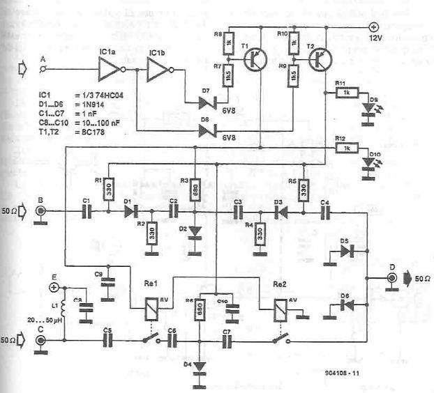
This antenna selector circuit diagram electronic project is constructed using standard electronic components and facilitates the switching between two FM antennas through a logic signal. The gates IC1b and IC1a manage the switching and interface between the required logic...
The author described assembling this circuit on a 1"*1" perf board, I actually laid out a small PC board with excellent results. In this era of surface mount components, I think a much smaller version can be laid out...
This audio-video circuit enables wireless audio and visual transmission to a television. The television functions as a receiver, eliminating the necessity for a separate monitor. It can also be connected to a VCR or CCD camera, and can be...
This document presents plans for a simple ground plane antenna that is effective in the FM band (88-108 MHz). It is constructed from a small plastic disk. The 6 x 6 loop antenna, designed by Graham Maynard, is highlighted...