
Optional Flip inverter circuit
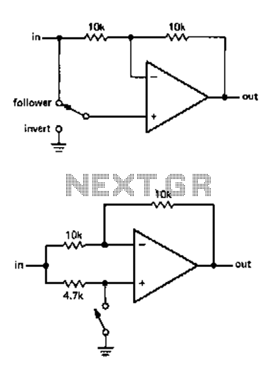
The described circuit functions as a phase inverter, facilitating the reversal of audio signals while maintaining control over the amplification characteristics. The operation of this circuit hinges on a switch that determines the output polarity, thereby influencing the voltage gain. The two versions of the circuit, A and B, present distinct approaches to achieving this function. Version B is favored for its reduced susceptibility to noise and instability, particularly in scenarios where the non-inverting input may not have a defined voltage level.
In version A, the potential issue arises when the switch is engaged, causing the non-inverting input to float temporarily. This floating condition can induce unpredictable voltages through the switch's wiring, leading to audible artifacts that may compromise the audio quality. Such disturbances manifest as hard clicks or murmurs, which are undesirable in professional audio applications.
The phase inverter circuit is crucial in audio power amplification systems, especially in multi-channel setups where maintaining the correct polarity of signals is essential for optimal performance. By implementing this circuit, users can easily rectify wiring errors or misconfigurations in speaker connections. Instead of physically reconnecting cables, the user can simply toggle the switch, providing a practical and efficient solution to phase issues in audio systems. This design consideration enhances the usability and flexibility of audio equipment, ensuring reliable operation in various configurations.Use the circuit shown we can reverse or flip the switch amplification without inversion. Voltage gain depending on the position of the switch. This may be +1 or -1. Changing circuit has two versions, A and B. I personally prefer B type, because there is no non-inverting input voltage level is uncertain at the moment. In one version, when the switch is flipped, with the non-inverting input is temporary floating, which may lead to unpredictable voltage indu1ced through the wiring of the switch, so that the hard click or murmur. This phase inverter circuit provides a polarity control is useful, for example, many channel audio power amplifier supplied (or queen Only) This function flips stage situation with a speaker wiring or installation error, because it is easier push a switch, instead of re-connecting cable.
Related Circuits
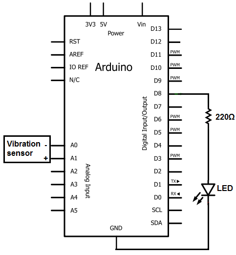
The sensors consist of a thin strip of piezoelectric material with a rivet at one end acting as a weight. When vibration occurs, the weight moves, stressing the piezo material, which generates a spike in voltage that can reach...
The FM302E-I-type FM transmitter exciter is manufactured by NEC Corporation, Japan, and features a 1210 motherboard. It utilizes direct frequency modulation of the carrier signal, employing phase-locked frequency stabilization and frequency synthesis techniques. The front power amplifier is based...
Is there a circuit that can be used to make a DC motor move randomly backward and forward, stop for a period, and then start again? Any assistance and ideas would be greatly appreciated. Research how to wire up...
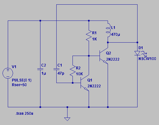
Four observations regarding the Joule Thief AA battery LED circuit. The schematic of the LED circuit illustrates the power source (V1), which symbolizes a depleted battery with only 1 volt remaining and an internal resistance. The Joule Thief circuit is...
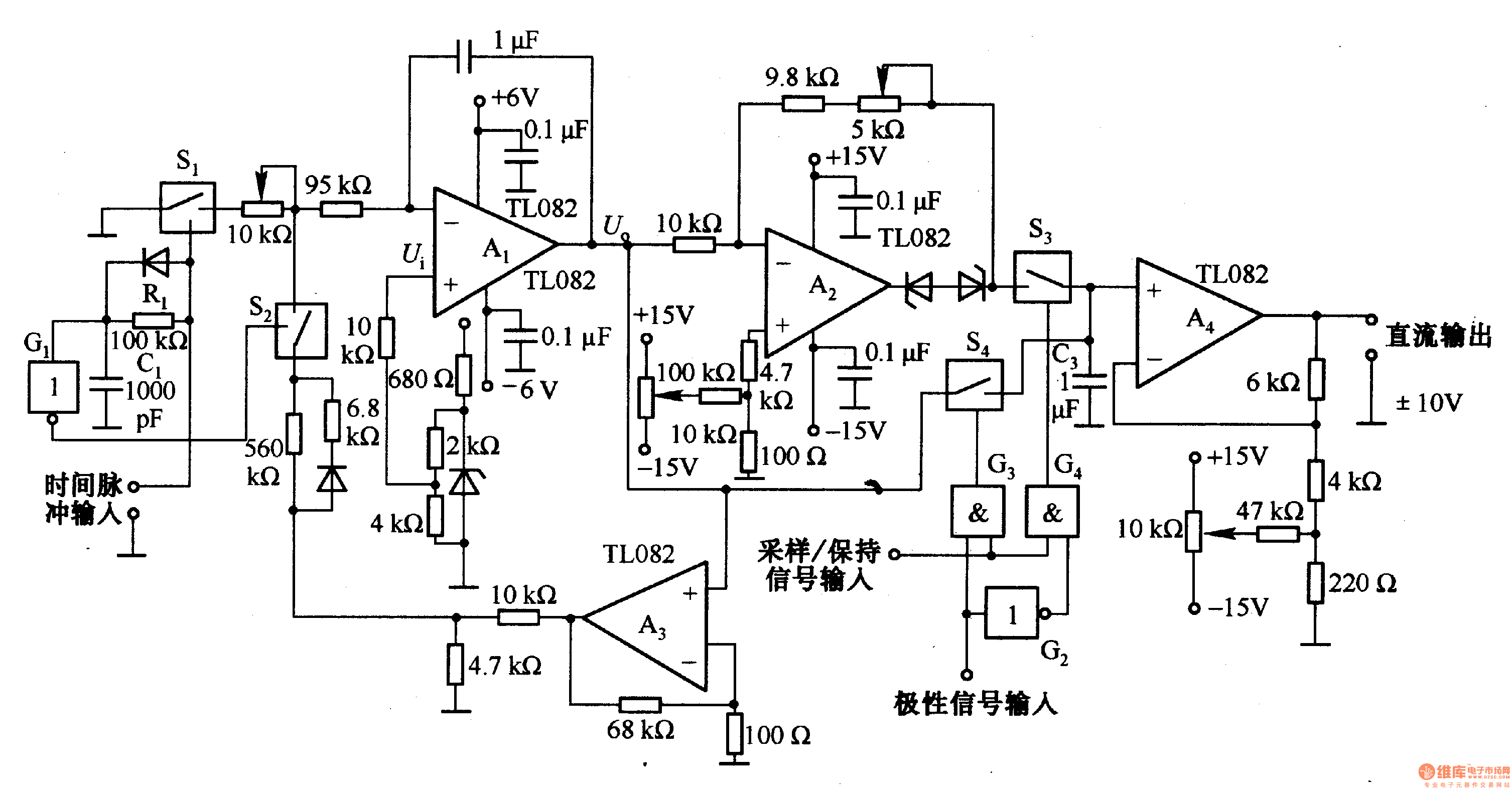
This circuit is designed for pulse width (time) to voltage conversion. According to the component parameters in the diagram, it can convert a pulse width of 0.1 seconds into an output voltage of 10V. When a conversion pulse is...

The I2C PIC Interfacing Tutorial circuit is relatively straightforward; however, it requires careful verification to ensure that all connections are correct before initial operation. The primary components utilized in this circuit include the PIC18F452 microcontroller, the 24LC02B EEPROM, and...