
Oscillator Fundamentals
A feedback oscillator is a critical component in various electronic applications, utilizing the principle of positive feedback to generate continuous waveforms. The basic operation involves an amplifier that receives a portion of its output signal back into its input. This feedback loop is crucial for establishing the conditions necessary for self-sustained oscillation.
In designing a feedback oscillator, several key parameters must be considered. The gain of the amplifier must be greater than one to ensure that the output signal reinforces the input signal. Additionally, the total phase shift around the feedback loop must be equal to zero or a multiple of 360 degrees at the frequency of oscillation. This condition is essential for achieving stable oscillations.
Common configurations of feedback oscillators include the Hartley oscillator, Colpitts oscillator, and the phase-shift oscillator. Each configuration utilizes different components, such as inductors and capacitors, to set the frequency of oscillation. For instance, the Hartley oscillator typically employs two inductors and a capacitor, while the Colpitts oscillator uses two capacitors and one inductor.
The design of a feedback oscillator also involves selecting appropriate components to ensure stability and performance. The choice of amplifier, whether it be a transistor or an operational amplifier, influences the oscillator's characteristics, including frequency stability, output waveform shape, and power consumption.
In summary, feedback oscillators are essential in generating oscillatory signals in electronic circuits, relying on positive feedback mechanisms to maintain continuous operation. Their design and implementation require careful consideration of component selection and circuit topology to achieve desired performance characteristics.Feedback Oscillator Positive feedback is used in oscillators to maintain running or oscillating. An oscillator is basically an amplifier which has a feedb.. 🔗 External reference
Related Circuits
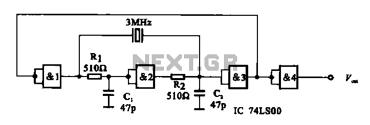
A crystal oscillator circuit is composed of several gates. Figure (A) illustrates a crystal oscillator circuit operating at 1 MHz, while Figure (B) depicts a 20 MHz crystal oscillator circuit. Figure (C) represents a variable crystal oscillator circuit with...
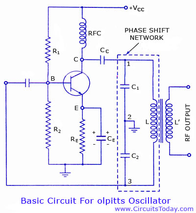
Colpitts oscillator circuit diagram and theory. Colpitts oscillator frequency equation. Colpitts oscillator using transistor. Colpitts oscillator using op-amp. The Colpitts oscillator is a type of electronic oscillator that generates sine waves and is widely used in various applications such as...
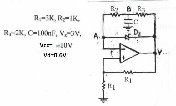
This circuit appears to be a Schmitt trigger oscillator. Based on the configuration of the resistors and capacitor, it is likely functioning as a sawtooth wave generator, with resistors R2 and R3 influencing the slope of the rising and...
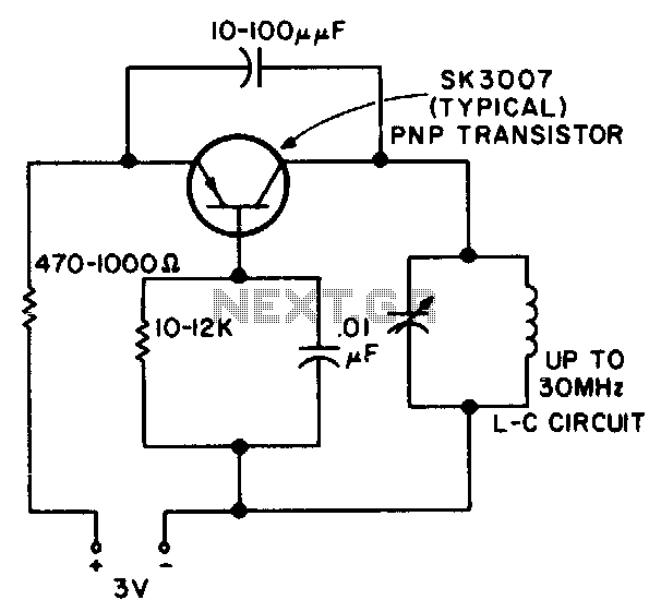
This RF oscillator is effective up to 30 MHz. An SK 3007 PNP transistor is recommended. The described RF oscillator circuit operates within a frequency range of up to 30 MHz, making it suitable for various applications in radio frequency...
A phase-locked loop (PLL) is widely utilized in telecommunications, control systems, and various other electronic applications. PLLs can be employed to demodulate frequency-modulated (FM) signals and generate a stable output frequency. A phase-locked loop is an essential feedback control system...

This is a circuit known as a Wien bridge oscillator. The circuit features both positive and negative feedback loops and operates under the control of an operational amplifier (op-amp). The oscillation frequency is determined by the RC time constant,...