
Oscillator IIV
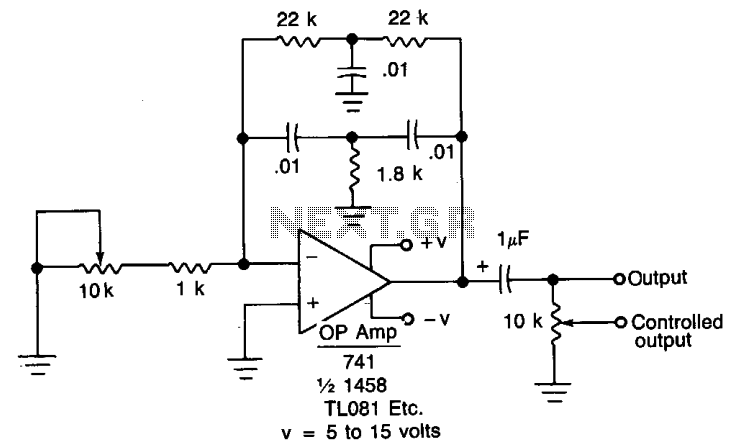
In this circuit configuration, the oscillator generates an AC signal that can interfere with the DC circuit's operation. To prevent this interference, a DC blocking capacitor is utilized. The capacitor allows AC signals to pass while blocking DC components, ensuring that the DC circuit functions correctly without being affected by the oscillator's output.
The potentiometer serves as a variable resistor that can be adjusted to control the amplitude of the AC signal reaching the load. Connecting the DC blocking capacitor in series with the wiper arm of the potentiometer allows for fine tuning of the output signal. The addition of a 10 kΩ potentiometer enhances the control over the signal, enabling precise adjustments to the output level. This configuration is particularly useful in applications where signal integrity is crucial, such as in audio processing or signal conditioning circuits.
The overall design ensures that the oscillator can effectively interface with the DC circuit while maintaining the desired output characteristics, providing flexibility in signal management and control. Proper selection of the capacitor value is essential to match the frequency response of the oscillator, while the potentiometer should be chosen based on the required range of output adjustment. This setup emphasizes the importance of component selection and configuration in achieving optimal circuit performance. When the oscillator is connected to a dc circuit then connect a dc blocking capacitor in series with the potentiometer's wiper arm. If fine output control is desired, add the 10 potentiometer. 🔗 External reference
Related Circuits

The circuit design is relatively straightforward. It features a Voltage Controlled Oscillator (VCO) utilizing the ICL8038 along with supplementary components, a sine and triangle output stage using the LT1210, and a CMOS-compatible output stage driven by the MOSFET driver...
Built around a single 8038 waveform generator IC, this circuit produces sine, square or triangle waves from 20Hz to 200kHz in four switched ranges. There are both high and low level outputs which may be adjusted with the level...
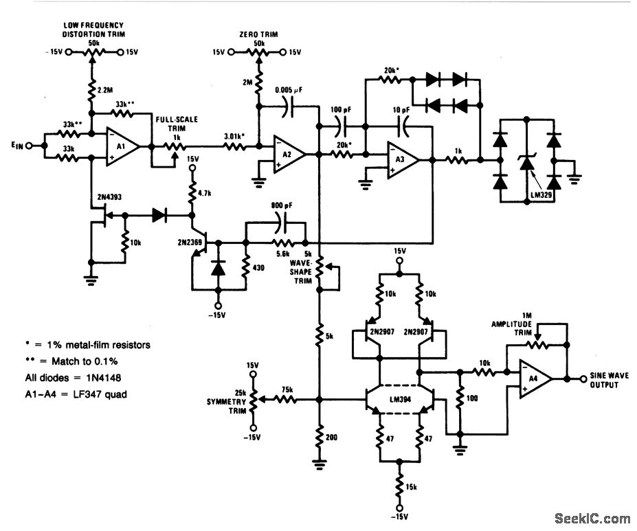
For a 0- to 10-V input, this circuit generates sine-wave outputs ranging from 1 Hz to 20 kHz, achieving linearity better than 0.2%. The distortion level is approximately 0.4%, and both the frequency and amplitude of the sine-wave output...
A tone generator operates on as little as 1.5 VDC using the Sallen-Key configuration. The tone generator will be applied to implement a phantom-powered signal source for testing balanced microphone inputs. Textbooks and web pages typically depict the Wien...
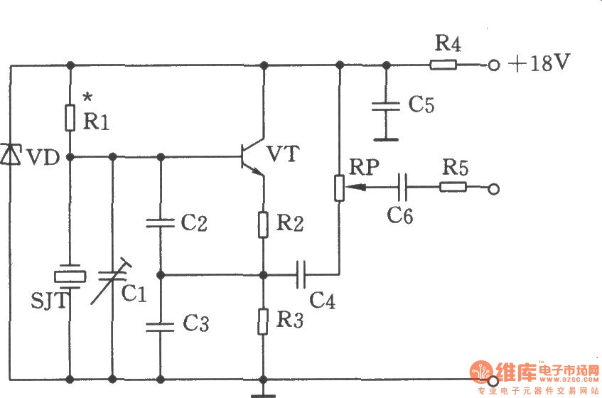
The figure illustrates the Colpitts oscillator circuit, which utilizes a base frequency crystal. The operating frequency is 1499 kHz, with the crystal SJT connected to both ends of capacitors C2 and C3. The emitter divider resistors R2 and R3...
Crystal oscillators are devices where a specially cut crystal regulates the frequency. Crystal-controlled oscillators are the standard method for maintaining the frequency of radio transmitting stations within their designated limits. These oscillators typically produce an output that is highly...