
Function Oscillator using 8083

This circuit utilizes the 8038 waveform generator integrated circuit (IC1) as the core component for generating various waveforms, including sine, square, and triangle waves, across a frequency range of 20Hz to 200kHz. The circuit design incorporates a four-range switch that allows the user to select the desired frequency range effectively. The output levels can be adjusted using a level control, providing flexibility for different applications.
The frequency generation relies on the internal squarewave oscillator of the 8038, which is modulated by external timing capacitors (C1 to C4) and a 10k potentiometer. It is crucial that the capacitors used in this application have a tolerance of 10% or better to ensure frequency stability. The square wave output from IC1 is then differentiated to create a triangular wave, which is subsequently shaped into a sine wave. The internal design minimizes the need for external components, enhancing the circuit's compactness and reliability.
For sine wave purity, two 100k preset resistors are employed to fine-tune the waveform, ensuring that the distortion remains below 1% when optimally adjusted. The circuit includes a single pole three-way rotary switch to select the waveform type, which is connected to a 10k potentiometer responsible for controlling the amplitude across all generated waveforms.
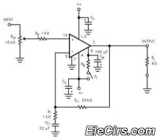
The output stage features an LF351 operational amplifier (IC2) configured as a direct-coupled non-inverting buffer. This configuration serves to isolate the waveform generator from the load, while also increasing the output current capability. The output attenuator is constructed using a 2.2k resistor in series with a 47-ohm resistor, allowing for precise control of output levels.
At the high output setting, the circuit can deliver a peak-to-peak voltage of approximately 8V for the square wave, while the maximum outputs for the triangle and sine waves are around 6V and 4V, respectively. The low amplitude settings are particularly beneficial for testing purposes, enabling output levels of 20mV and 50mV to be easily achieved, which is essential for interfacing with sensitive amplifiers and other electronic devices.Built around a single 8038 waveform generator IC, this circuit produces sine, square or triangle waves from 20Hz to 200kHz in four switched ranges. There are both high and low level outputs which may be adjusted with the level control. This project makes a useful addition to any hobbyists workbench as well. The waveform generation is produced by IC1. This versatile IC even has a sweep input, but is not used in this circuit. The IC contains an internal squarewave oscillator, the frequency of which is controlled by timing capacitors C1 - C4 and the 10k potentiometer.
The tolerance of the capacitors should be 10% or better for stability. The squarewave is differentiated to produce a triangular wave, which in turn is shaped to produce a sine wave. All this is done internally, with a minimum of external components. The purity of the sine wave is adjusted by the two 100k preset resistors. The wave shape switch is a single pole 3 way rotary switch, the wiper arm selects the wave shape and is connected to a 10k potentiometer which controls the amplitude of all waveforms.
IC2 is an LF351 op-amp wired as a standard direct coupled non-inverting buffer, providing isolation between the waveform generator, and also increasing output current. The 2.2k and 47 ohm resistors form the output attenuator. At the high output, the maximum amplitude is about 8V pk-pk with the square wave. The maximum for the triangle and sine waves is around 6V and 4V respectively. The low amplitude controls is useful for testing amplifiers, as amplitudes of 20mV and 50mV are easily achievable.
The two 100k preset resistors adjust the purity of the sine wave. If adjusted correctly, then the distortion amounts to less than 1%. 🔗 External reference
Related Circuits
The coil has been enhanced with additional turns, necessitating an improvement in insulation. Epoxy was chosen as the insulating material, with an increased quantity applied over the soldered connections. To ensure the reliability and performance of the coil, the additional...
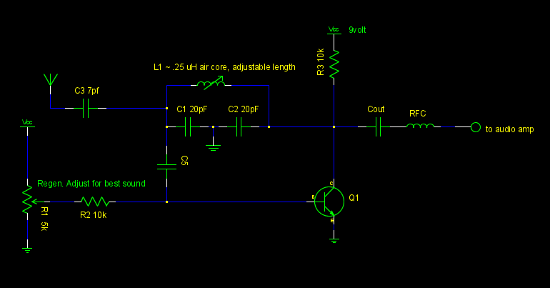
A common emitter Colpitts oscillator was constructed using variable capacitors for C1 and C2, and a few turns of wire wrapped around a pencil for the inductor L. Resistors R1 and R2 were replaced with a trimmer potentiometer to...
The PC board has been designed to accept either a PIC16F84A or PIC16F628. With the introduction of the 628 to the world market, it has taken over from the PIC16F84A and we will be ceasing to design projects for...
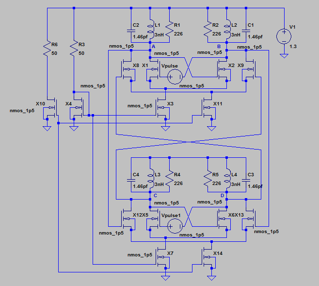
This post provides an analysis and design of two oscillators functioning in quadrature. It begins with a brief explanation of the circuit's operation, followed by a design implementation in HSPICE. The content is derived from the oscillators chapter of...
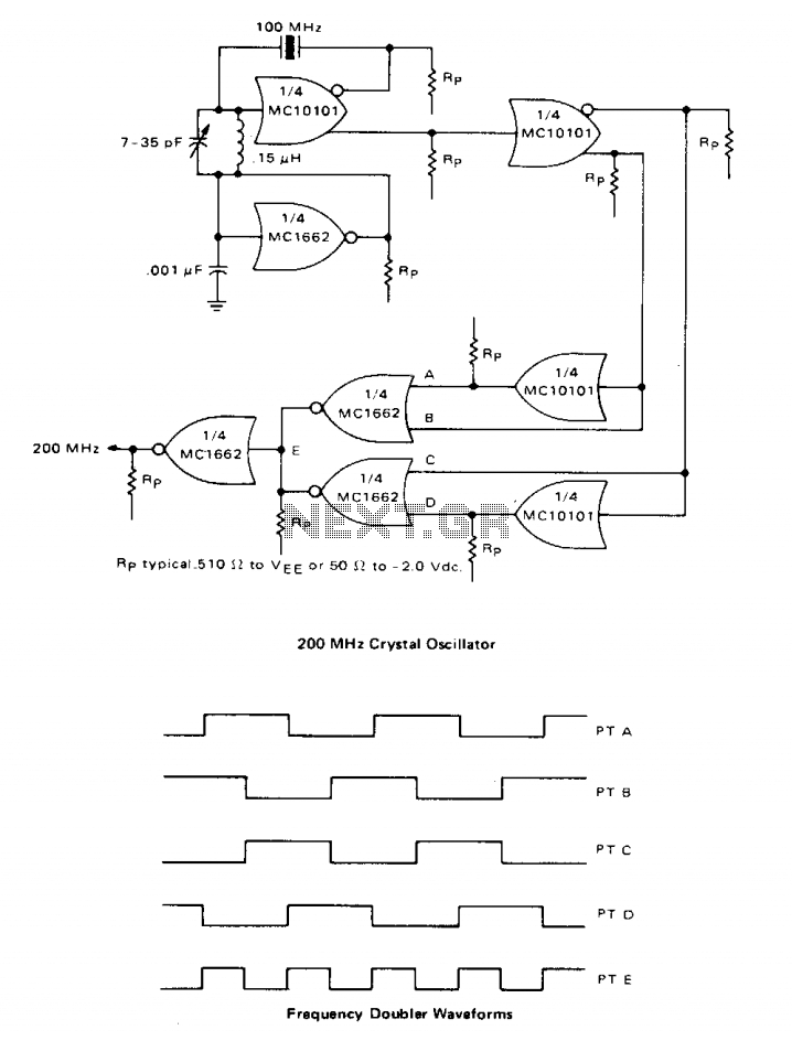
A high-speed oscillator can be created by integrating an MECL 10 crystal oscillator with an MECL III frequency doubler. One section of the MC10101 is configured as a 100 MHz crystal oscillator, with the crystal placed in series within...
The LM3886 high-performance audio power amplifier circuit schematic is a crucial component in sound reproduction within audio systems. This audio power amplifier utilizes the LM3886 integrated circuit to enhance sound quality and output. The LM3886 is a high-performance audio power...