
Transistor Pulse Generator
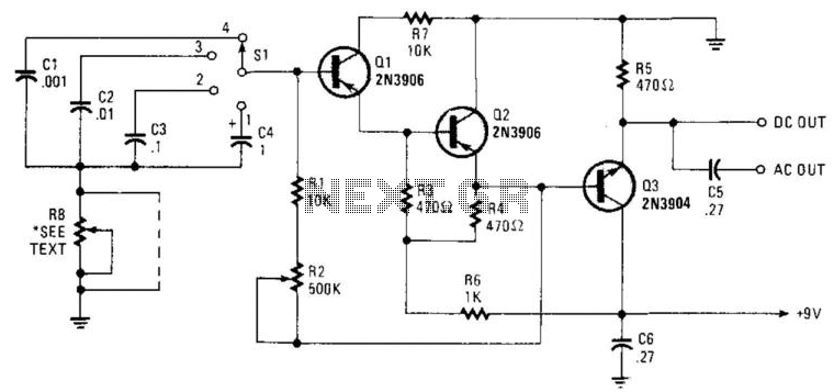
This circuit is designed to produce a series of narrow pulses with a frequency range from 2 Hz to 50 kHz, making it suitable for various applications such as timing, signal generation, and modulation. The core of the circuit relies on capacitors C1 through C4, which are configured to define different frequency ranges through a process known as decoding. This allows the circuit to produce distinct pulse frequencies by altering the charge and discharge cycles of these capacitors.
Resistors R1 and R2 play a crucial role in controlling the charging time of the capacitors. R1 is typically fixed, providing a baseline resistance, while R2 is a potentiometer that allows for fine-tuning of the frequency output. By adjusting R2, the user can manipulate the time constant of the RC (resistor-capacitor) network, thereby altering the frequency of the generated pulses.
Additionally, resistor R8 is included in the design to control the pulse width of the output signals. The pulse width can be varied between 7 ms and 10 ms, depending on the specific requirements of the application. In scenarios where precise pulse width is not critical, R8 can be omitted from the circuit to simplify the design and reduce component count without significantly affecting performance.
Overall, this circuit provides a versatile solution for generating narrow pulses across a wide frequency spectrum, with adjustable parameters to suit various electronic applications. Seven-V narrow pulses from 2 Hz to 50 kHz are produced by this circuit. CI through C4 provide frequency ranges i n decode steps. Rl and R2 control the charging time of CI through C4. R2 is a potentiometer used to set the frequency. R8 controls pulse width. Pulse width varies from 7 & to 10 ms. Depending on the frequency, R8 can be deleted if it is not needed. 🔗 External reference
Related Circuits

Generators that do not use fuel to operate provide 24 hours of electricity for continuous use. In the early days of this invention, a significant issue arose: the battery powering the generators would deplete within 20 to 30 minutes...
This circuit utilizes a PIC microcontroller and an internal 1 kHz sinewave table to generate an accurate sinewave. It requires only a few external components for filtering. The sinewave benefits from high frequency accuracy due to its generation from...
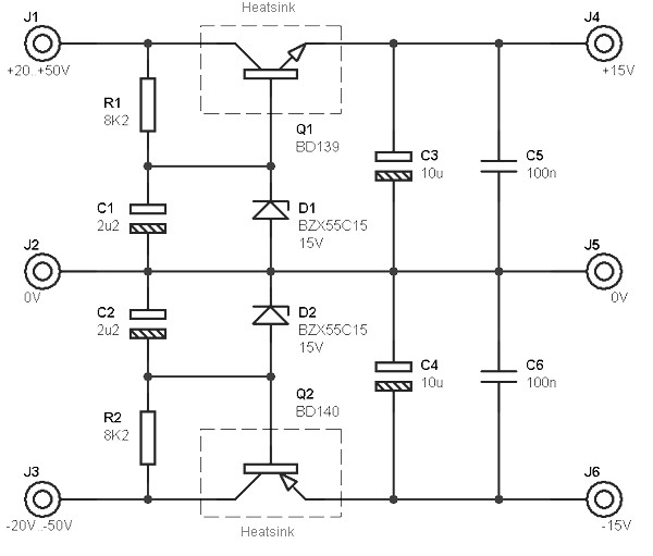
This circuit is designed to be integrated into an existing circuit, such as an audio amplifier, which already supplies symmetric voltages of +20V/-20V and +50V/-50V. The schematic diagram is derived from a dual polarity power supply circuit providing +/-...
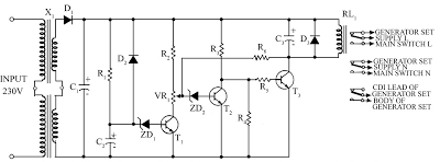
Due to the energy crisis, load shedding has become a common issue in several countries. Sudden power fluctuations, surges, and high voltage can damage sensitive household appliances such as TVs, VCRs, VCPs, and music systems. This circuit offers protection...

This circuit design generates a stable 1 kHz sine wave using an inverted Wien bridge configuration with components C1-R3 and C2-R4. It offers a variable output, low distortion, and low output impedance to ensure good overload capability. The circuit...
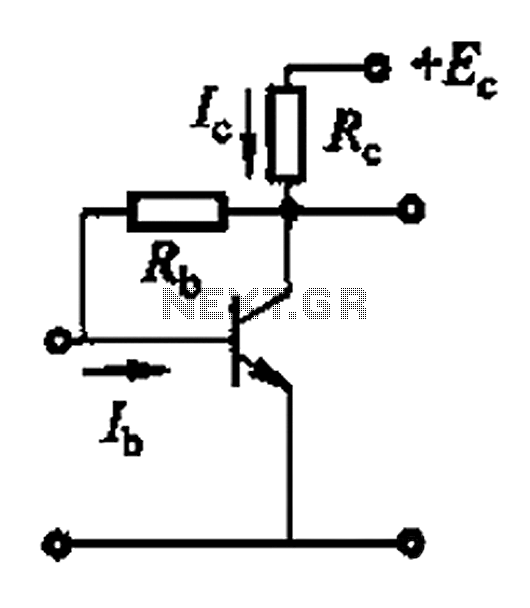
Basic reference bias circuit using a transistor with negative voltage feedback. The basic reference bias circuit utilizing a transistor with negative voltage feedback is designed to provide a stable output voltage or current that is largely independent of variations in...