
Wien bridge oscillator
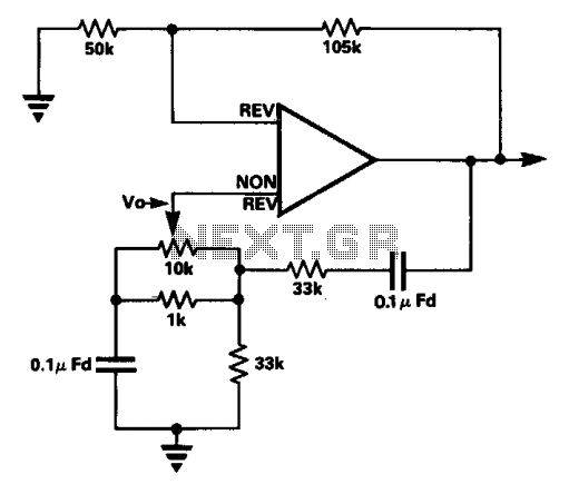
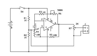
The described circuit features a frequency trimming component that plays a crucial role in maintaining stability while allowing for fine-tuning of frequency characteristics. The quadrature arrangement with the bridge voltage V0 ensures that modifications to the trimming component have a negligible impact on the overall attenuation, which is essential in applications where precise signal integrity is required. This design choice effectively circumvents the complexity and potential performance issues associated with dual-gang components, which are typically used for simultaneous adjustments in frequency and amplitude.
The implementation of a high-gain amplifier is vital for achieving the desired loop gain, which is set just at the threshold of oscillation. This careful calibration allows for optimal performance without introducing instability into the circuit. Metal film feedback resistors are selected for their excellent thermal stability and low noise characteristics, which contribute to the overall reliability and accuracy of the circuit.
By removing the need for an automatic gain control mechanism, such as a thermistor, the design simplifies the circuit architecture while enhancing its performance. This is particularly beneficial in applications where temperature variations might otherwise affect gain stability. The limited frequency variation range is a deliberate design choice, ensuring that the circuit remains focused on a specific operational bandwidth, which can be critical in precision applications such as communication systems or sensor interfaces.
Overall, this circuit design exemplifies a balance between simplicity and functionality, providing a robust solution for frequency adjustment while minimizing the potential for signal degradation.In the circuit the frequency trimming component is arranged so that the voltage across it is in quadrature with the voltage V0 from the bridge so that as it is adjusted the attenuation of the bridge only changes a little, avoiding the need for a two gang component. The range of variation of frequency is very limited. By using a high gain amplifier and metal film feedback resistors the loop gain can be set so that the unit just oscillates and the use of an automatic gain setting component, a thermistor for example, is eliminated. 🔗 External reference
Related Circuits
This is the first oscillator that was built. Various resources such as books, magazines, and online schematics were reviewed. Most of the designs encountered were either Colpitts or Hartley oscillators. While these designs are relatively straightforward, they require specific...
This document presents the design of an audio oscillator that operates at approximately 1 kHz. The circuit is likely sourced from EMFRD, as Wes's book contains a wealth of valuable circuits. This versatile oscillator serves as a signal source...
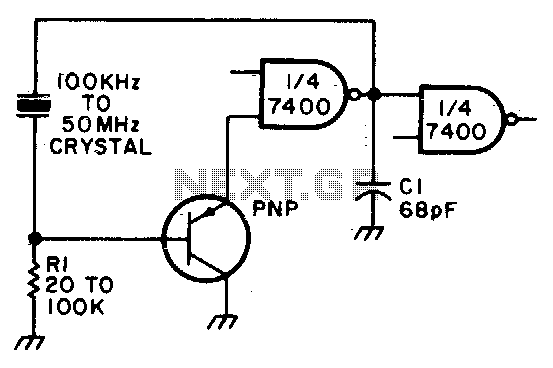
Adjust Rl for approximately 2 volts at the output of the first gate. Additionally, adjust Cl for optimal output. In the context of electronic circuit design, the output voltage of a gate, such as a logic gate or operational amplifier,...
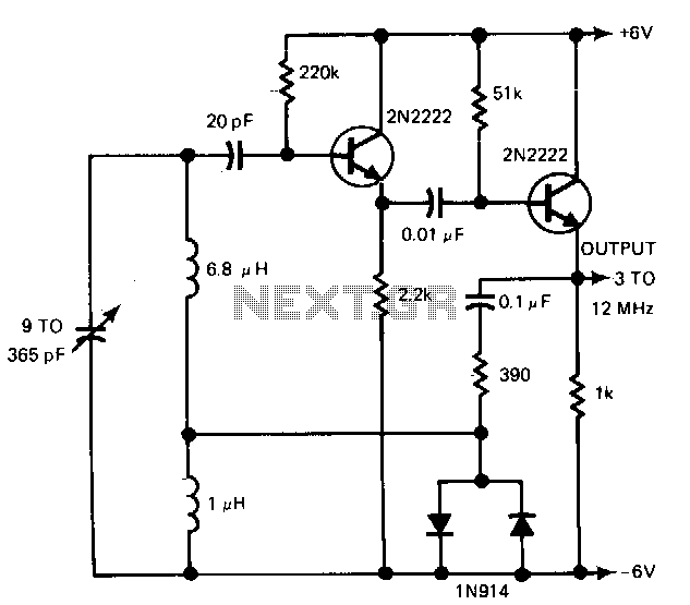
The gain control enables the oscillator to maintain a nearly constant output across its range. The circuit operates within a frequency range of 160 kHz to 12 MHz while producing a consistent amplitude. The oscillator circuit described utilizes a gain...
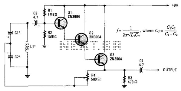
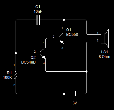
Essentially, this is a Hartley oscillator utilizing a triple-emitter follower, suitable for audio and low radio frequencies. The frequency is determined by the components, and at 1 kHz, a typical capacitor value would be 4.7 µF tantalum, although this...
An attempt has been made to follow an instructable for some time; however, understanding its schematic remains challenging. The issue is not a lack of knowledge regarding the symbols used. In electronic schematics, symbols represent various components and their connections...