
Maximum Minimum Voltage Indicator

The circuit is designed to compare three input voltages, labeled A, B, and C, each capable of varying between -4V and +4V. The primary function of this circuit is to determine and visually indicate which of the three input voltages is the greatest by activating one of three indicator lights, typically LEDs.
To achieve this, a series of operational amplifiers (op-amps) can be employed in a comparator configuration. Each op-amp is connected to two of the input voltages, allowing for pairwise comparisons. For instance, one op-amp can compare voltage A with voltage B, while another compares voltage B with voltage C, and the third compares voltage C with voltage A. The outputs of these comparators will indicate which voltage is higher in each pair.
The outputs from the op-amps can be fed into a priority encoder or a simple logic circuit that will determine which voltage is the highest among the three. Based on this logic, the corresponding output will activate one of the three indicator LEDs. Additional circuitry may be included to ensure that only one LED is lit at any given time, preventing conflicts in the outputs.
Power supply considerations must also be taken into account, ensuring that the circuit can operate effectively within the specified voltage range. Proper decoupling capacitors should be used to stabilize the op-amps and prevent oscillations.
In summary, this circuit not only serves the purpose of voltage comparison but also provides a clear visual representation of the highest voltage among the inputs, making it useful in various applications where voltage monitoring is critical.This circuit indicates which of three voltages in the range from about about -4V to about +4V at A, B and C is the highest by lighting one of three in.. 🔗 External reference
Related Circuits
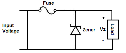
An overvoltage protection circuit is designed to safeguard electronic components from excessive voltage that could potentially cause damage or destruction. This project involves constructing a straightforward yet effective overvoltage protection circuit using a fuse and a zener diode as...
If you have ever wanted a high-voltage generator to create impressive lightning effects, conduct Kirlian photography experiments, or experiment with neon lights, this project is ideal. It describes a laboratory pulse generator utilizing an auto-ignition coil, capable of delivering...
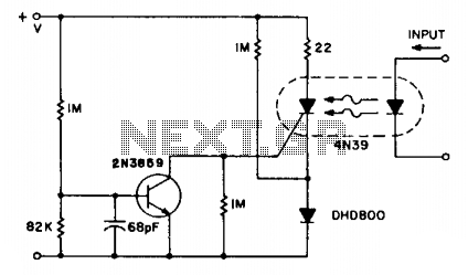
The SCR coupler circuit offers increased sensitivity to input signals as demonstrated. This enables the utilization of the more economical 4N39 (H11C3) with the drive currents exceeding 7 mA provided by the input circuit. The SCR coupler circuit is designed...
This circuit demonstrates that microprocessors, PCs, and modern ultra-accurate Digital-to-Analog Converters (DACs) are excessive for controlling four relays in sequence based on a control voltage ranging from 2.4 V to 12 V. By utilizing equal resistors in a ladder...
Field bus technology and intelligent instrument technology are currently two of the most rapidly evolving technologies in automation and control. In the realm of field bus technology, the CAN bus has established itself as a relatively fast communication standard...
Under the loading condition of the resistance, the output voltage (Uo) variable range is from 30V to 36V, with a maximum output current (Imax) of 2A. When the input voltage (U2) changes from 15V to 21V, the voltage regulation...