
Pal decoder
The circuit design involves several critical components and configurations aimed at enhancing video signal quality for HAM radio applications. The NMS8280 serves as the central processing unit, interfacing with a PAL decoder and encoder to manage the conversion between RGB and CVBS formats. The low-pass filter, which begins attenuation at 3 MHz, plays a pivotal role in filtering the luminance signal, while the capacitor placed over the filter improves the separation of color and luminance signals.
The 4053 multiplexer is essential for switching between the internal RGB signal and the incoming video signal, ensuring that the output remains stable even under weak input conditions. The delay introduced by the 74HC74 is crucial for maintaining synchronization between the select signal and the video output, preventing potential artifacts in the displayed image.
The phase correction implemented between the encoder and decoder addresses the issue of color inversion, specifically targeting the red channel, which had shown inconsistent behavior. This adjustment, combined with the attenuation of the burst signal, enhances overall color fidelity and saturation.
In summary, this circuit design effectively addresses the challenges associated with video signal processing in the context of HAM radio, ensuring high-quality signal transmission while maintaining synchronization and color integrity.After some years i started using the NMS8280 again for HAM radio purpose. When sending a signal in the air, radio amateurs should always identify by giving their callsign, this is also the case for sending a video signal. I wrote a program using the WBASS assembler which shows a scrolltext, this can be downloaded here. Unfortunately the incoming video signal is first converted to RGB, and converted back later after superimposing. The PAL decoder in this MSX is not very good, the encoder to convert RGB to CVBS is quite okay. At first sight the picture improved by placing a capacitor over the filter just before the PAL decoder, this filter separates the colour (c) (4. 43MHz) signal from the luminance (y) signal. For the y path, the video signal is passed through a lowpass filter which starts attenuating around 3MHz.
This gives loss in sharpness. I tried to improve this filter, but it`s not easy to keep the delay of the y and c path equal, and too high frequencies will give aliasing while digitizing. Another work around is to simply switch between the unconverted inputsignal and the signal coming from the MSX video processor after the PAL encoder.
This can be done by a 4053 for example. Normally the internal PAL encoder from the MSX will switch between the RGB signal of the MSX and the RGB version of the incoming video signal. The MSX video processor (VDP) determines when to display the internal or external signal. When this signal is used to switch the CVBS signals with the 4053, we are done for 80%. The select signal from the VDP is related to the RGB output of the VDP, after converting to CVBS the signal will be delayed for about 200ns.
A 74HC74 is used to delay this digital select signal 2 clock cycles of the DHCLK of the VDP, otherwise the 4053 would switch too early. For example one white vertical line from X=100, Y=0 to X=100, Y=200 will result in superimposing a black line at X=99.
At the beginning of a line a short pulse of 4. 43MHz (burst) is given to synchonisse the PAL decoder inside a monitor or TV. Both CVBS signals are synchonised in the sense that the line number and the position in the line are corresponding, but not really for this colour signal. In this circuit the sync and the burst of the internal video will always be selected, in case of a weak input signal, the MSX picture won`t suffer from it.
This means the monitor or TV will lock on the colour signal of the MSX. I did not think of this problem until i noticed the colours were messed up. Luckily the PAL encoder in the MSX uses the 4. 43MHz generated by the PAL decoder, which is synchonised with the burst of the incoming video signal, so at least the colours stayed stable, they did not change. I made a small testprogram to display vertical lines with several colours, the video signal of a second MSX was used as input signal: The strange thing is, when the phase is wrong you would expect an inversion of both red and blue.
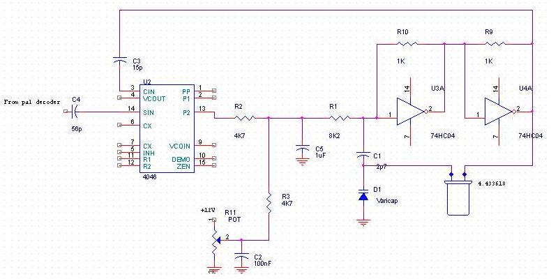
In this situation blue seems okay, but only red inverted. To get a clear idea of what happend i made a small, simple circuit to be able to create any phase shift of the 4. 43Mhz signal using a PLL. The last one has the best colour saturation, in there is a phase error the colour intensity will be less.
The second one has different colours but still not right. After taking a closer look into a schematic of a PAL decoder, the phase of only red turned out to be shifted from line to line the wrong way. The PAL encoder turns the phase in exactly the opposite way compared to the input signal. Inverting the H/2 line between decoder and encoder solved this. To finish, a small phase correction to the encoder optimizes the colour. When comparing the original signal and the signal which is routed through the MSX, there is still some lack of colour.
To solve this, the burst is attenuated by pulling it to ground by a transistor trough a 220Ohm resistor after the 1k resistor. The colour sig 🔗 External reference
Related Circuits
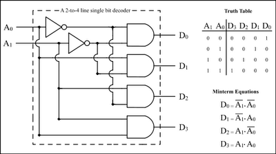
The Encoder and Decoder are different types of combinational circuits used to convert binary information to decimal, octal, and hexadecimal formats, and vice versa. A decoder is a combinational circuit that converts n-bit binary information into 2^n unique outputs....
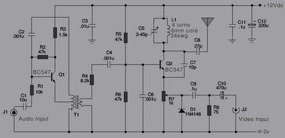
The following is a series of simple TV transmitters utilizing negative sound modulation and PAL video modulation. This design is suitable for countries employing TV systems B and G. Inductor L1 can be constructed using 24 SWG wire, consisting...
The MT8870 is a complete DTMF receiver that integrates both the band-split filter and digital decoder functions. The filter section employs switched capacitor techniques for high and low group filters, while the decoder utilizes digital counting methods to detect...
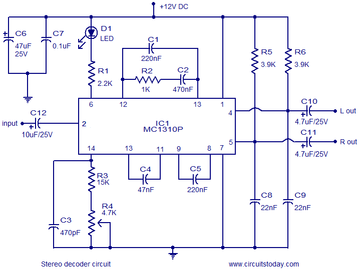
A simple FM stereo decoder circuit utilizing the MC1310P integrated circuit (IC). It operates at 12V and provides a channel separation of 40dB, making it suitable for stereo FM receivers. The FM stereo decoder circuit based on the MC1310P IC...
In FM stereo transmission, the left and right audio channels are encoded into sum (left + right) and difference (left - right) signals. This encoding allows mono FM receivers to be compatible with stereo transmissions. The mono receiver reproduces...
Can I use the following circuit, or is there any special IR decoder IC and schematics available? If the decoder supports any remote, that is acceptable. However, I want to control a variable resistor via IR without using relays,...
Warning: include(partials/cookie-banner.php): Failed to open stream: Permission denied in /var/www/html/nextgr/view-circuit.php on line 713
Warning: include(): Failed opening 'partials/cookie-banner.php' for inclusion (include_path='.:/usr/share/php') in /var/www/html/nextgr/view-circuit.php on line 713