
Peak Detector
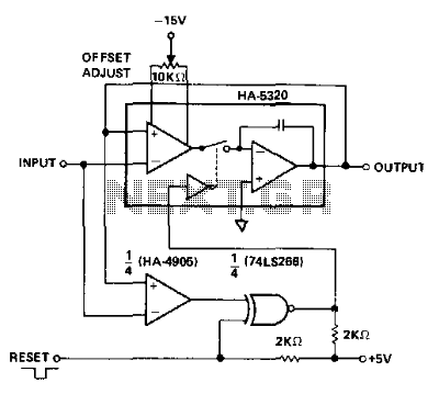
The HA-5320 is a high-speed analog signal processing component that exhibits a propagation delay of approximately 100 ns. This characteristic is critical for applications involving time-varying signals, where maintaining an accurate voltage difference between the input and output is essential. The circuit's ability to detect changes in voltage polarity is particularly useful for applications involving peak detection. When the input signal slope transitions from positive to negative or vice versa, the output voltage reflects this change, making it possible to sample and hold the peak values of the signal.
To implement a peak detection function, a comparator is integrated into the circuit. This component is responsible for monitoring the input signal's polarity changes, thus enabling the circuit to respond dynamically to variations in the input waveform. The exclusive NOR gate serves an essential role by providing a reset capability, allowing the HA-5320 to revert to sample mode when necessary. This feature is particularly beneficial in scenarios where continuous monitoring of peak signals is required.
The design includes specific connections aimed at detecting positive peaks, with the flexibility to reverse the comparator inputs for detecting negative peaks. This adaptability enhances the circuit's functionality across a broader range of signal conditions. Additionally, to ensure reliable operation, an offset voltage must be incorporated. This offset is crucial for creating a sufficient voltage step that can effectively trigger the comparator after the input signal surpasses a peak.
The operational frequency range of this circuit extends from below 100 Hz up to the point where slew-rate limiting becomes a factor. Slew-rate limiting occurs when the rate of change of the signal exceeds the capabilities of the circuit to respond effectively, which can result in distortion or loss of signal integrity. The circuit is designed to capture the amplitude of voltage pulses accurately, provided that the duration of the pulses is long enough to allow the signal to reach its peak value. This characteristic is essential for applications that require precise measurements of transient signals, such as in telecommunications or instrumentation systems. An analog signal requires about 100 ns to propagate through the HA-5320. For time-varying signals, this assures a voltage dif ference between input and output. Also, the voltage changes polarity when the signal slope changes polarity (passes a peak). This behavior makes the circuit a possible sample/hold peak detector, by adding a comparator to detect the polarity changes. The exclusive NOR gate allows a reset function which forces the HA-5320 to the sample mode. The connections shown detect positive peaks; the comparator inputs can be reversed to detect negative peaks.
Also, the offset must be introduced to provide enough step in voltage to trip the comparator after passing a peak. This circuit works well from below 100 Hz up to the frequency at which slew-rate limiting occurs. It captures the amplitude of voltage pulses, provided that the pulse duration is sufficient to slew to the top of the pulse.
🔗 External reference
Related Circuits
The metal detector consists of a probe oscillator, a reference oscillator, an audio amplifier, and various other components, as illustrated in the schematic. The probe oscillator is made up of transistors V1 and V2, a detection coil L1, a...
To drill a hole in a wall, it is essential to ensure that no electrical wiring is present. The device illustrated in Figure 1 is capable of detecting electrical wiring in walls or ceilings. Resistor R1 serves to protect...
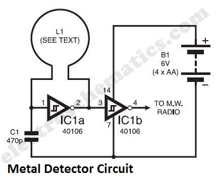
The metal detector circuit presented here exemplifies simplicity while demonstrating effective functionality. It utilizes a single 40106 hex Schmitt inverter IC, a capacitor, a search coil, and batteries. A connection from IC1b pin 4 must be made to a...
The metal detector circuit comprises an oscillator and a sound-light alarm circuit. The oscillator circuit includes an inductor (L), a capacitor (C1), a sensor switch integrated circuit (IC1) that integrates the oscillator, detector, comparator circuit, and peripheral components. The...
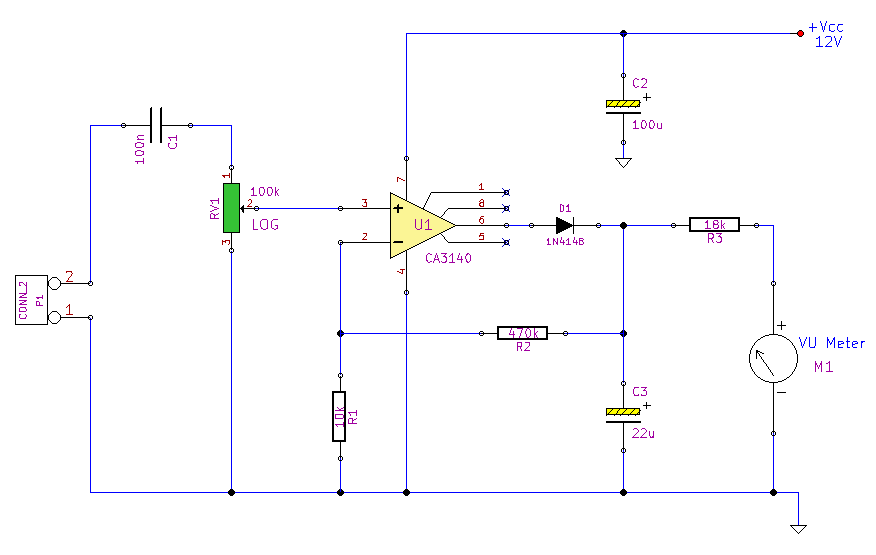
This simple circuit, designed with a minimal component count, indicates peak audio response on an analog meter, similar to a tape recorder's meter. It employs an operational amplifier configured as a non-inverting amplifier, with the addition of a diode...

The 555 timer is configured as a monostable multivibrator that requires a negative-going trigger. If the input pulse is positive-going, it can be inverted using an inverter circuit, which can be constructed with either an inverting gate or a...
Warning: include(partials/cookie-banner.php): Failed to open stream: Permission denied in /var/www/html/nextgr/view-circuit.php on line 713
Warning: include(): Failed opening 'partials/cookie-banner.php' for inclusion (include_path='.:/usr/share/php') in /var/www/html/nextgr/view-circuit.php on line 713