
Peak detector
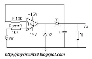
The circuit design consists of a resistor network with a value of 10k ohms, which is commonly used for current limiting or voltage division. The choice of capacitors, 1µF and 10µF, suggests that this circuit may involve timing applications or filtering, where the capacitance value can significantly influence the circuit's performance characteristics. The presence of a diode indicates that the circuit may include rectification or protection elements, ensuring that current flows in a specific direction or preventing reverse polarity damage.
To achieve the desired output, it is essential to verify the connections in the schematic. The orientation of the diode must be correct, as reversing it will prevent current flow. Additionally, the values of the capacitors should be chosen based on the application requirements; for instance, a larger capacitor (10µF) will provide a longer discharge time compared to a smaller one (1µF), affecting the timing or filtering behavior of the circuit.
Further troubleshooting steps include checking the power supply connections, ensuring that the circuit is powered correctly, and measuring the voltage across various components to identify any discrepancies. It is also advisable to confirm that all components are functioning correctly and are rated for the appropriate voltages and currents. If the circuit is part of a larger system, interactions with other components should be considered, as they may affect the overall performance.I tried the circuit below, but i couldn`t make the output.. Plz help me with corrections. In schematic: Resistors - 10k capacitor - I tried both 1uf and 10 uf Diode .. 🔗 External reference
Related Circuits
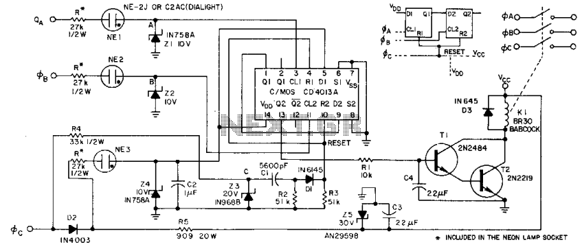
This circuit derives its supply voltage, Vcc, and Vdd from the AC supply. This factor, along with the neon lamps and zener diodes in the phase inputs, establishes a 50% threshold that detects low voltage or the absence of...
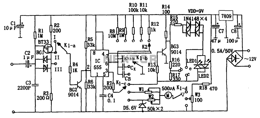
The frequency detection circuit utilizes a transistor line, adjustable via a preset switch K1, to convert capacitance and frequency measurements. The K1 switch is positioned to detect capacitance. The circuit comprises components including a 555 timer, resistors R8 to...
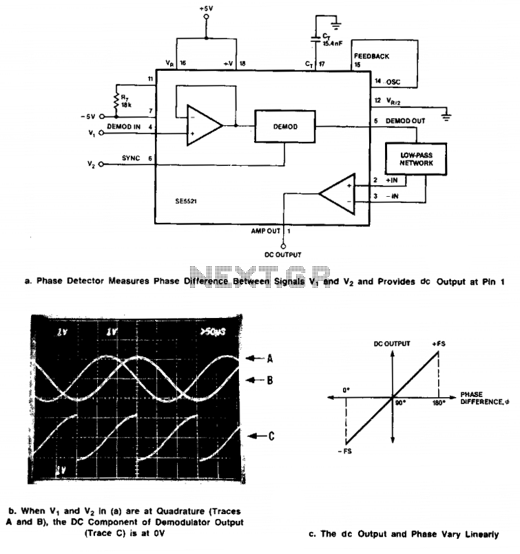
Signals of identical frequency are applied to the sync input (Pin 6) and to the demodulator input (Pin 4). The demodulator operates as a phase detector, with the output DC component being proportional to the phase difference between the...
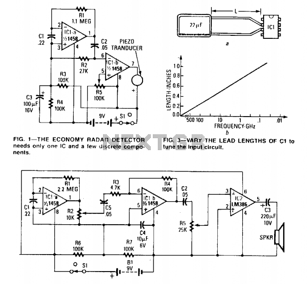
The circuit can be tuned to respond to signals between 50 MHz and 500 GHz. The economy model is illustrated in Figure 1, while the deluxe model is depicted in Figure 2. The first operational amplifier (op-amp) in each...
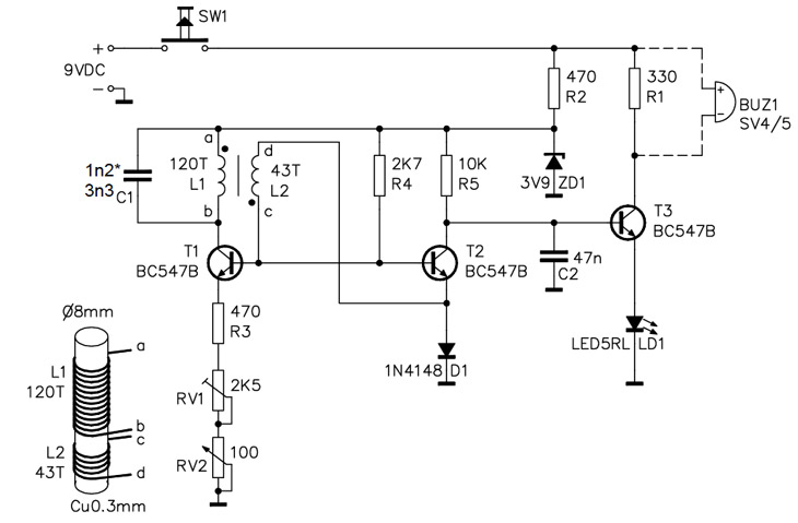
A simple home project can quickly become problematic if it encounters electric cables, gas, or water pipes, or the central heating system. Using a metal detector allows one to check for metal objects within walls, ceilings, or floors beforehand....

Useful for liquids level detection and proximity devices. Up to 50 cm range, optional relay operation. This circuit is useful in liquids level or proximity detection. It operates detecting the distance from the target by reflection of an infra-red...