
pen transmitter

The spy pen FM transmitter circuit is designed to be compact and discreet, allowing for covert audio transmission. The circuit utilizes a crystal oscillator to ensure stable frequency output, which is crucial for effective FM transmission. The integration of the circuit within a ballpoint pen casing enhances its portability and concealment, making it ideal for surveillance applications.
The main components of the circuit typically include a crystal oscillator, an audio input stage, a modulator, and an RF output stage. The crystal oscillator generates a precise frequency, while the audio input stage captures sound through a microphone. The modulator then combines the audio signal with the carrier frequency from the oscillator, creating an FM signal suitable for transmission. The RF output stage amplifies this signal before it is transmitted via an antenna, which can be discreetly integrated into the pen's design.
Power supply considerations are also essential for this circuit. A small battery, such as a button cell, can be used to power the circuit, ensuring that it remains compact. Careful attention must be paid to the power consumption of each component to maximize battery life.
Overall, the construction of this spy pen FM transmitter circuit combines functionality with stealth, making it a valuable tool for those requiring discreet audio transmission capabilities. Proper assembly and testing of the circuit are critical to ensure reliable operation and compliance with legal regulations regarding audio transmission.This Spy Pen FM Transmitter Circuit Can Be Built In A Ballpoint Pen. Crystal Controlled.. 🔗 External reference
Related Circuits

This is a schematic of a synthesized Phase-Locked Loop (PLL) for a low-power FM transmitter. It can also be utilized with other circuits, provided that the loop filter response, components, VCO tank circuit, and appropriate thumbswitch programming keys and...

This circuit can be adjusted to operate within the frequency range of 87-108 MHz, achieving a transmission distance of approximately 20 to 30 meters. The design incorporates a pair of BC548 transistors, which, while not specifically designated as RF...
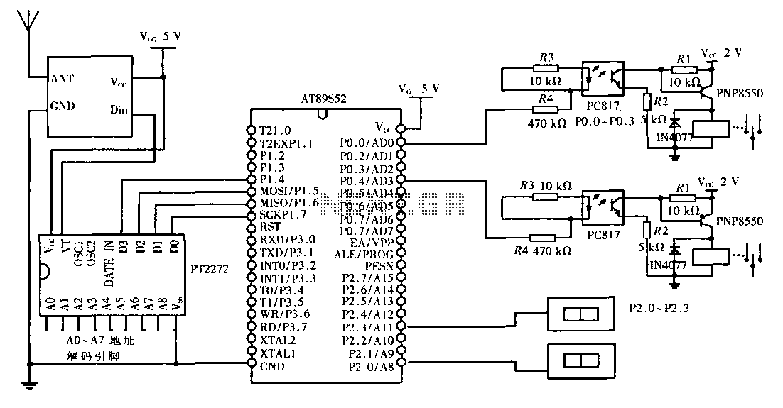
This design aims to create a long-distance wireless remote control switch lighting control system, which consists of a transmission system and a reception system. The system utilizes wireless transceiver modules for RF transmission and reception. The transmitting portion mainly...

This FM transmitter circuit employs four radio frequency stages: a VHF oscillator built around the transistor BF494 (T1), a preamplifier constructed with the transistor BF200 (T2), a driver using the transistor 2N2219 (T3), and a power amplifier based on...
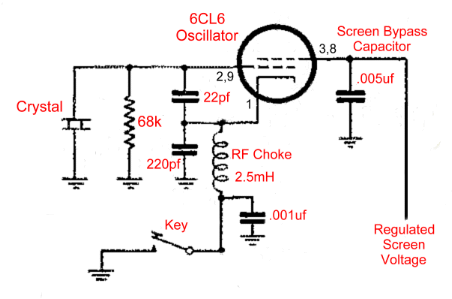
The operation of the 6CL6 transmitter is quite sophisticated despite the simple appearance of the circuit. The core of the circuit is the electron-coupled crystal oscillator. This circuit integrates the functions of an oscillator and amplifier into a single...
The modulator and oscillator comprise two NPN transistors. The base of the modulator transistor is powered by a bidirectional current source, with the voltage range for the high condition restricted by a saturating PNP collector connected to the pin...