
Switchless NiCd-NiMH Battery Charger

This circuit design effectively addresses the limitations of conventional battery chargers by employing the LM317 voltage regulator in a constant current configuration. The circuit's simplicity eliminates the need for variable resistors or complex switching mechanisms, making it a robust solution for charging different battery types.
The LM317 operates by maintaining a constant output current determined by the resistor network formed by R1, R2, and R3. The choice of these resistors directly influences the charging current, ensuring that it remains within safe limits for the specific battery being charged. The inclusion of diodes D1 and D4 enhances the circuit's reliability by providing necessary biasing for the transistor and preventing reverse current flow, respectively.
Thermal management is crucial in this design, particularly when charging larger capacity batteries that may require higher currents. The power dissipation across the resistors and the LM317 must be calculated to prevent overheating, necessitating the use of a heat sink.
The design also emphasizes electrical safety by recommending the use of a mains adapter with a DC output, which provides a safer alternative to traditional transformer-based chargers. This consideration is essential in ensuring user safety and prolonging the lifespan of the charging circuit.
In summary, this circuit offers a practical, efficient, and reliable method for charging NiCd batteries while addressing common issues associated with traditional chargers, including battery life and electrical safety.This circuit may be used to replace the single current limiting resistor often found in dirt cheap battery chargers. The alternative shown here will eventually pay off because you no longer have to throw away your NiCds after three months or so of maltreatment in the original charger.
The circuit diagram shows an LM317 in constant-current configur ation but without the usual fixed or variable resistor at the ADJ pin to determine the amount of output current. Also, there is no switch with an array of different resistors to select the charge currents for three cell or battery types we wish to charge: AAA, AA and PP3 (6F22).
When, for example, an empty AAA cell is connected, the voltage developed across R1 causes T1 to be biased via voltage dropper D1. This results in about 50 µA flowing from the LM317`s ADJ pin into the cell, activating the circuit into constant-current mode.
D4 is included to prevent the battery being discharged when the charger is switched off or without a supply voltage. The charging current I is determined by R1/R3/R3 as in R(n) = (1. 25 + Vsat) / I where Vsat is 0. 1 V. The current should be one tenth of the nominal battery capacity ” for example, 170 mA for a 1700-mAh NiCd AA cell.
It should be noted that PP3` rechargeable batteries usually contain seven NiCd cells so their nominal voltage is 8. 4 V and not 9V as is often thought. If relatively high currents are needed, the power dissipation in R1/R2/R3 becomes an issue. As a rule of thumb, the input voltage required by the charger should be greater than three times the cell or battery (pack) voltage.
This is necessary to cover the LM317`s dropout voltage and the voltage across R(n). Two final notes: the LM317 should be fitted with a small heat sink. With electrical safety in mind the use of a general-purpose mains adapter with DC output is preferred over a dedicated mains transformer/rectifier combination. Be the first of your friends to get free diy electronics projects, circuits diagrams, hacks, mods, gadgets & gizmo automatically each time we publish.
Your email address & privacy are safe with us ! 🔗 External reference
Related Circuits
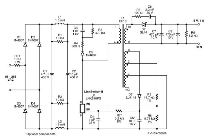
A very simple 5-volt constant voltage, constant current (CV/CC) universal-input power supply for cell phone or similar charger applications can be designed using the LNK616PG product from the LinkSwitch-II family. This low-cost charger adapter accepts a wide range of...
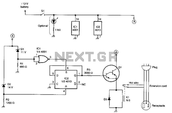
This circuit utilizes a pair of Zener diodes to monitor the voltage of a 12-V battery. When the voltage drops below 11 V, diode D1 ceases to conduct, causing pin 3 of flip-flop IC2 to go high. This action...
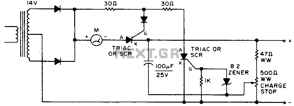
Adjust by setting the 500-ohm resistor while attached to a fully charged battery. The circuit involves a 500-ohm resistor that is to be adjusted while it remains connected to a fully charged battery. This setup is typically used in applications...
Most individuals are unaware that there are typically over a dozen battery backup systems present in their homes. The average American has around 18 battery-backed devices in their household. These battery backup systems protect crucial, expensive, or portable electronics...
Most Bulle clocks require their magnets to be rejuvenated before they can operate correctly with a standard 1.5V cell. The first significant magnet material was cobalt-chrome steel, introduced in 1921. Prior to this, carbon steel was hardened through heating...
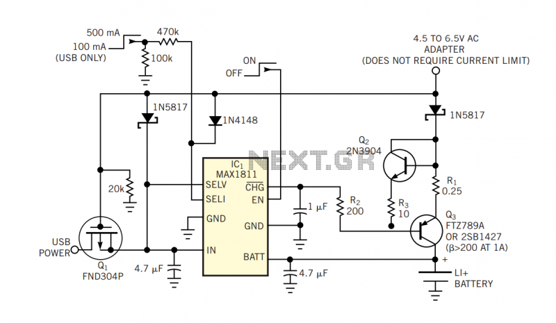
The popular USB interface can charge a portable device while transferring data. But for high-capacity batteries, the 500-mA output current of USB hosts and powered hubs greatly extends the charging time. Thus, a system that accepts charging power from...