
Phone Busy Indicator schematic
The circuit described operates as a telephone line indicator, providing visual feedback on the status of a phone line. The primary component responsible for this functionality is an LED (D6) that indicates whether the phone line is busy or free.
When the phone line is busy, the voltage across the line drops, causing the LED to turn off. Conversely, when the line is free, the voltage rises to approximately 60 V, which allows the FET (T1) to conduct, thereby turning the LED on.
The circuit employs a voltage divider configuration to manage the high voltage present on the telephone line. This divider is crucial for scaling down the voltage to a safe level that can be processed by the rest of the circuit, including the FET and any associated components. The use of a rectifier bridge ensures that the circuit can handle the AC voltage from the telephone line without being affected by polarity, making it versatile for different types of connections.
A zener diode and capacitor are included in the design to stabilize the voltage and protect the circuit from voltage spikes that may occur on the line. It is important that these components are correctly oriented to ensure proper operation.
The circuit is designed to be powered by a 9 V battery, which is suitable for driving the LED at a current of approximately 10 mA. This current level is adequate for ensuring that the LED is sufficiently bright for visibility while maintaining a low power consumption from the battery.
Overall, this circuit provides a simple yet effective means of indicating the status of a telephone line, utilizing common electronic components to achieve reliable performance.This indicator shows whether the phone is busy or not. When the line is busy, LED D6 off. The line voltage at points A and B attached. By the rectifier bridge behind the connection, the polarity does not matter. The voltage of 60 V is the voltage divider. The voltage at the voltage divider to the negative mass (capacitor and zener diode are not incorrectly signed). When the line is not busy, the line is approximately 60 V. The FET T1 will conduct and the LED lights up. Is the phone listed, then drops the voltage and the FET is not conducting and the LED goes out. When connecting to the telephone line that is approximately 60 V, which is not really low-voltage can be expected. The circuit is best with a 9 V battery powered. If the LED is running a current of 10 mA. 🔗 External reference
Related Circuits
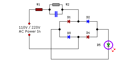
Compact yet highly functional, this is a straightforward and efficient LED circuit designed to operate directly from the AC mains supply, ranging from 100 volts to 230 volts. This LED circuit utilizes a few essential components to achieve efficient...
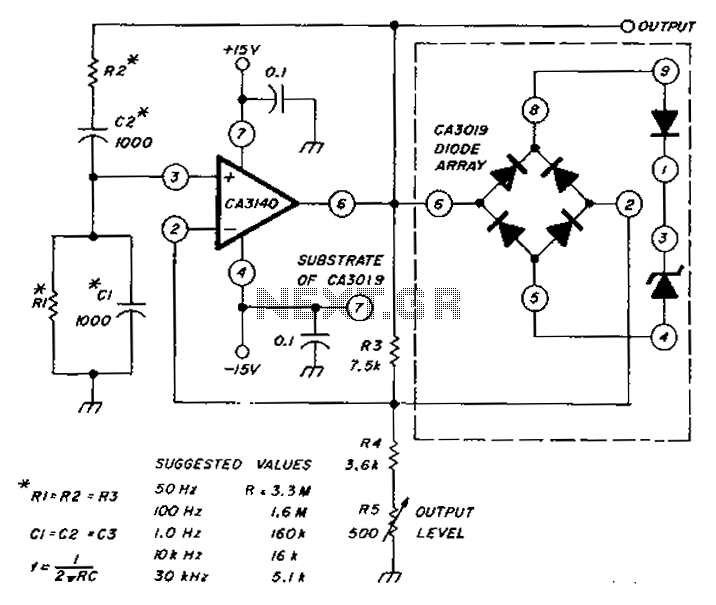
The circuit diagram utilizes a CA3140 operational amplifier and a diode array to generate a low distortion sine wave. A table specifies the values of resistors (R) and capacitors (C), enabling frequency access ranging from 50 Hz to 30...
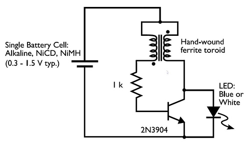
In the circuit diagram for the Joule Thief, the common point of the toroid is the connection at the top of the hand-wound ferrite toroid, located in the upper right of the diagram. This connection leads to the positive...
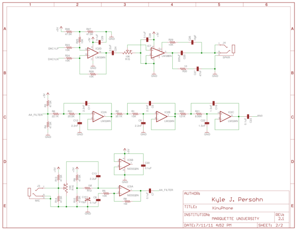
XinuPhone promotes hands-on interactive learning that is both cross-discipline and application-oriented. As a research tool, XinuPhone is a versatile and open-source platform useful for benchmarking experimental methods against industry standards. Furthermore, the XinuPhone platform features inexpensive commodity hardware that...

The circuit incorporates components Q, C, and ZD, which are responsible for the bias and buffer stages. Its primary objective is to ensure stable MOSFET gate operation and provide an offset voltage through a voltage buffer amplifier stage with...

The LMP91200 is a configurable sensor analog front-end (AFE) designed for managing low-power analytical sensing applications, specifically for 2-electrode sensors. This device offers all the necessary functionality to detect changes based on a delta voltage from the sensor. It...