
PIC16F628 4 RGB LED PWM Controller
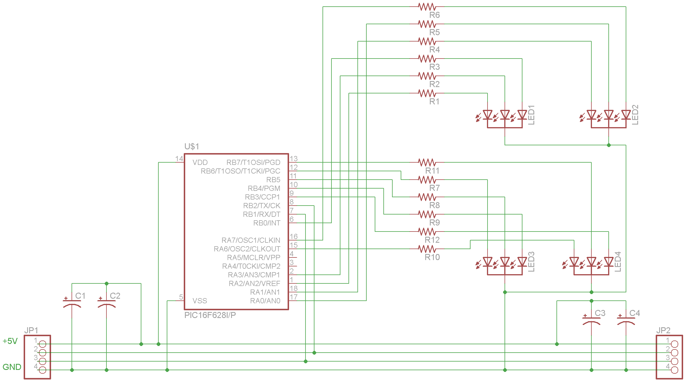
The schematic features the PIC16F628 microcontroller, which operates at a frequency of 4 MHz, making it suitable for various applications requiring moderate processing capabilities. The internal USART facilitates serial communication, allowing the microcontroller to interface with other devices. The inclusion of a pull-up resistor on RA5 is critical for ensuring proper logic levels during operation, particularly when the pin is configured as an input. The printed circuit board (PCB) design was executed by BatchPCB.com, known for their cost-effective PCB manufacturing services.
The total expense of $32.36 for four boards reflects the economical approach to prototyping, enabling the designer to test the circuit without significant investment. The design process included an iterative approach, with the first revision revealing the necessity for the pull-up resistor, which highlights the importance of thorough testing and validation in electronic design. Future revisions will incorporate this correction, improving the reliability of the circuit.
The firmware implemented on the microcontroller supports eight distinct commands, providing flexibility for various applications. The removal of the self-test command demonstrates a consideration for memory management within the firmware, ensuring that the most critical functions remain available. The source code serves as a valuable resource for understanding the operational commands and their implementation, offering insights into the programming logic and structure used in the firmware design. Overall, this project exemplifies the process of designing, prototyping, and refining electronic circuits while leveraging cost-effective manufacturing solutions.Here is the full schematic for the driver. I chose to use a PIC16F628 as the microcontroller because it is cheap, has a internal oscillator (4 MHz) and an internal USART. NOTE: There is an error in this schematic and a pull-up resistor on RA5 (pin 4 in the schematic) is necessary.
See the bottom of the post for an updated schematic and board. I de cided I would try getting a PCB printed for the first time, so I got boards created at BatchPCB. com for $5 each. The total for 4 boards shipped was $32. 36 (4 x $5 for the boards and $12. 36 for shipping and handling). They took a long time to arrive, but the quality was well worth the wait. NOTE: There is an error on the first revision of the board and a pull-up resistor on RA5 (pin 4 in the schematic above) is necessary. You can see how I compensated for the mistake in the second picture below (look on the back of the upper-left board).
This will be corrected in future revisions. See the bottom of the post for an updated schematic and board. The current firmware has 8 commands (the 9th, self-test was removed to save space). See the source code for the firmware for how the commands are implemented, but here is some example usage: 🔗 External reference
Related Circuits
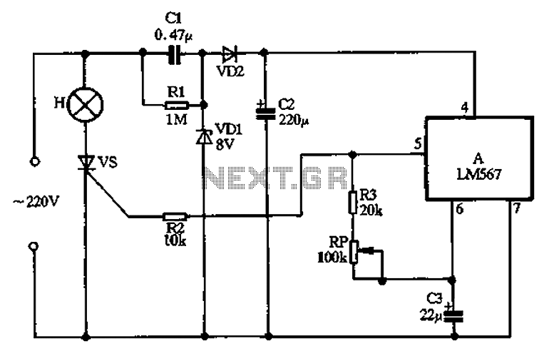
Cl, VDI, VD2, C2 form a simple capacitive step-down voltage regulator circuit with a rectifier output providing approximately 8V DC voltage for the LM567. A 5.6-foot manifold is connected. Resistors R3, RP, and capacitor C3 create an ultra-low frequency...
Here's how to make a good charger for a sealed lead-acid battery (this will NOT work with NiCad batteries) that’s faster (because it allows more current into the battery initially) and safer (because it uses lower voltage when the...
The simplest of all motor controllers (besides a straight on/off switch) is the contactor controller. I designed this contactor controller for use in my electric scooter project. It is based around three 12V relays, two 12V batteries, two switches...
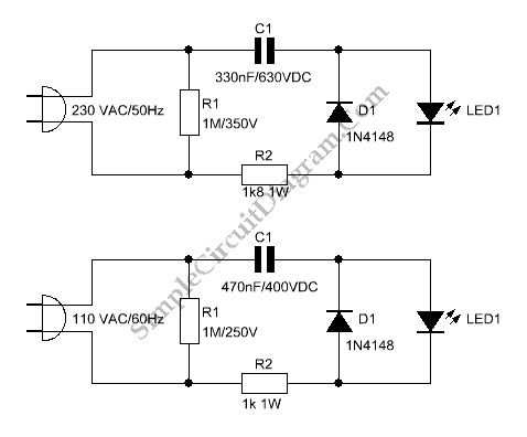
Typically, an LED is powered by a DC supply; however, this circuit enables the LED to be powered by an AC supply. This circuit can serve as a power indicator for a water pump. The circuit for powering an LED...
Cooling an instrument or device can enhance the signal-to-noise ratio (SNR) and extend the product's lifespan. For instance, the dark-and-noise signal of an infrared detector's output at room temperature can be significantly reduced when cooled. A custom cooling device...
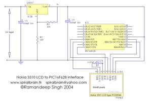
This project demonstrates the interfacing and operation of the Nokia 3310 LCD using the PIC16F628 microcontroller. The programming is executed in Hi-Tech C, with the character table incorporated within the source code. The Nokia LCD features a resolution of...