
PIC Based RS485 Multiplexer
The described circuit utilizes a PIC 16F84 microcontroller to serve dual functions as both an encoder and decoder within a communication system. This microcontroller is well-suited for such applications due to its programmability and capability to handle sufficient I/O operations. The choice of using the RS-485 communication standard, facilitated by DS26C31 and DS26C32 drivers, allows for robust data transmission over long distances, specifically over a 350-meter cable. RS-485 is particularly advantageous in environments where noise immunity and differential signaling are crucial.
The implementation requires only five I/O pins from the PIC 16F84, which indicates an efficient use of microcontroller resources. While a smaller 8-pin device, such as the PIC 12C508, could have sufficed, the 16F84 offers the flexibility of reprogramming, which can be beneficial for future modifications or updates to the system without needing to redesign the hardware.
The circuit design is adaptable, permitting modifications for varying data bit lengths and the integration of different communication interfaces, such as RS-232 or fiber optic connections. This flexibility enhances the circuit's applicability across various systems and requirements. The schematic would typically include the microcontroller connected to the RS-485 drivers, with appropriate pull-up and pull-down resistors to ensure signal integrity, as well as power supply connections to support the operation of the components.
In summary, the described circuit is a versatile and efficient solution for long-distance communication, leveraging the capabilities of the PIC 16F84 microcontroller and RS-485 standard, while allowing for future scalability and adaptability to different communication protocols.I decided to implement this using a PIC 16F84 for both an encoder and decoder, and use RS-485 drivers (DS26C31 and DS26C32) to drive the 350m cable. I only needed five I/O pins per PIC, so this could have been implemented using the smaller 8pin 12C508 device, but the 16F84 has the advantage of being reprogrammable, and PCB size or cost wasn`t an issue anyway.
The design presented here can be easily modified for any number of bits and any desired interface RS-232, Fibre optic, almost anything. 🔗 External reference
Related Circuits
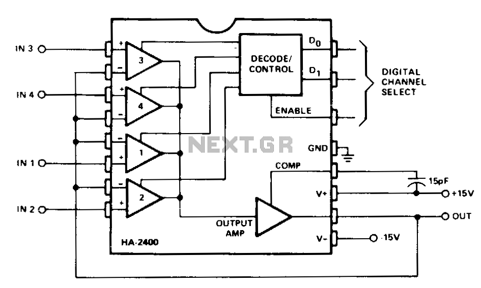
This circuit is utilized for analog signal selection or time division multiplexing. The feedback signal places the selected amplifier channel in a voltage follower (non-inverting unity gain) configuration, providing very high input impedance and low output impedance. The single...

This circuit is designed for sound detection and generates an output signal when sound is detected. This output can trigger another circuit that activates an alarm, making it suitable for security applications. The circuit employs a condenser microphone to...
The controller is a prototype and works well in my plane with 7 cells and a Graupner-Speed 600. The described controller is a prototype designed for use in a model aircraft, specifically optimized to operate with a battery pack consisting...
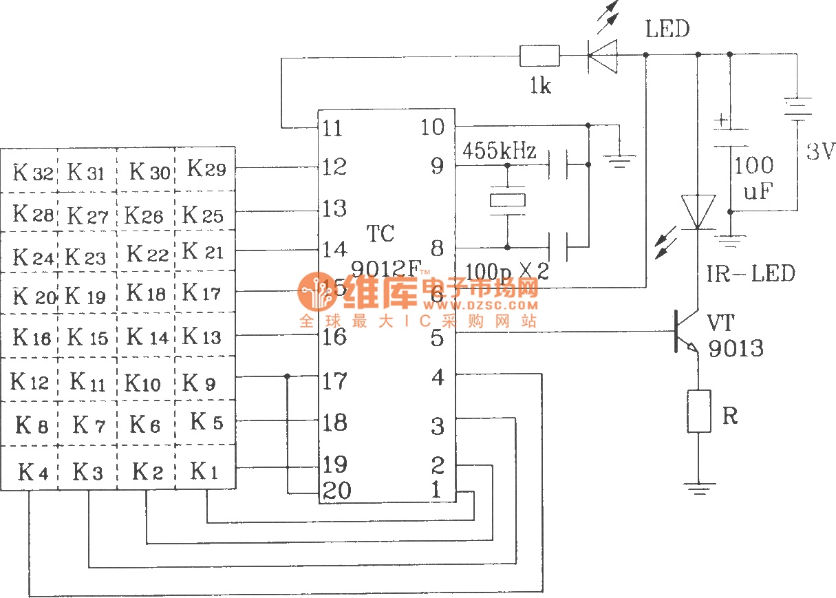
The TC9012 is a specialized off-screen remote control code transmitter. It incorporates an oscillator, divider timing generator, system code latch, data storage, key scan input, key scan output, and carrier control and output units. The internal 8-bit system code...
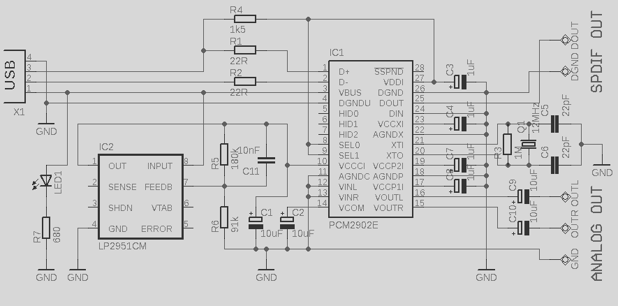
This circuit is a quality preamplifier with a built-in USB DAC designed for the Leachamp power amplifier. The schematic is based on the PCM2902 datasheet. The circuit includes a DAC and ADC, SPDIF input and output, and features three...
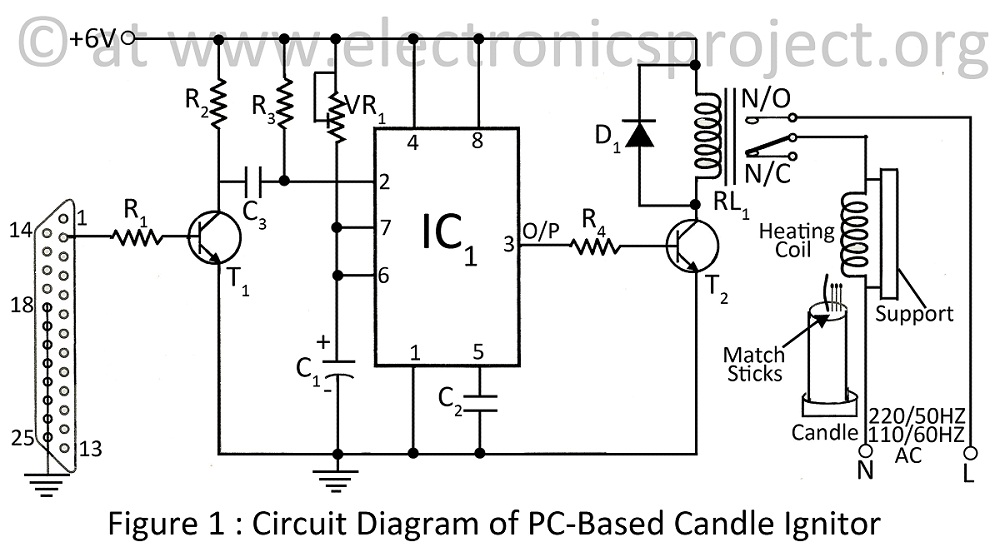
A PC-based candle ignitor is a verified project designed for computer students, utilizing a 555 timer circuit to ignite a candle. The project includes a computer circuit diagram and software code written in C. The PC-based candle ignitor project integrates...
Warning: include(partials/cookie-banner.php): Failed to open stream: Permission denied in /var/www/html/nextgr/view-circuit.php on line 713
Warning: include(): Failed opening 'partials/cookie-banner.php' for inclusion (include_path='.:/usr/share/php') in /var/www/html/nextgr/view-circuit.php on line 713