
op amp based sound detector circuit

This sound detection circuit utilizes a condenser microphone, which is known for its high sensitivity due to its powered nature. The microphone captures sound waves from the surrounding environment and converts them into an electrical signal. This signal is then amplified by the 741 op-amp, which is configured as an inverting amplifier. The inverting configuration allows for the manipulation of the signal phase, effectively inverting the output signal compared to the input.
Resistor R1 plays a crucial role in setting the gain of the op-amp, thus allowing for fine-tuning of the circuit's sensitivity to sound. By adjusting R1, the user can optimize the circuit for various sound levels, ensuring reliable detection in different environments. The capacitors C1 and C2 serve to filter out any unwanted DC offset that may be present in the signal, allowing only the alternating current (AC) component, which contains the sound information, to pass through to the output stage.
The output transistor Q1 is responsible for driving the subsequent alarm or notification circuit. The output signal taken from the collector of Q1 will be an inverted version of the amplified signal from the op-amp, which may need to be considered when interfacing with other components in the system. Overall, this circuit is an effective solution for sound detection applications, particularly in security systems where timely alerts are essential.This is a circuit that can be used for detecting sounds and providing an output signal when a sound is detected. This output signal may be fed to another circuit that sets off an alarm when the signal is received. This circuit is therefore useful in security applications. This is the figure of the circuit; The circuit uses a condenser microphone t o pick up sounds from the environment. This is a powered microphone, which makes it more sensitive than ordinary microphones. The microphone transforms the sound waves into an electronic signal that is fed to the 741 op amp. The 741 op amp in this circuit is configured as a single-supply inverting amplifier. Adjust R1 to maximize the sensitivity of your circuit. C1 and C2 are used to block the DC component of the signals, so that only the AC component carrying the sound information reaches the output transistor Q1. Note that the output, which is taken from the collector of Q1, is inverted with respect to the output of the 741 amplifier.
🔗 External reference
Related Circuits
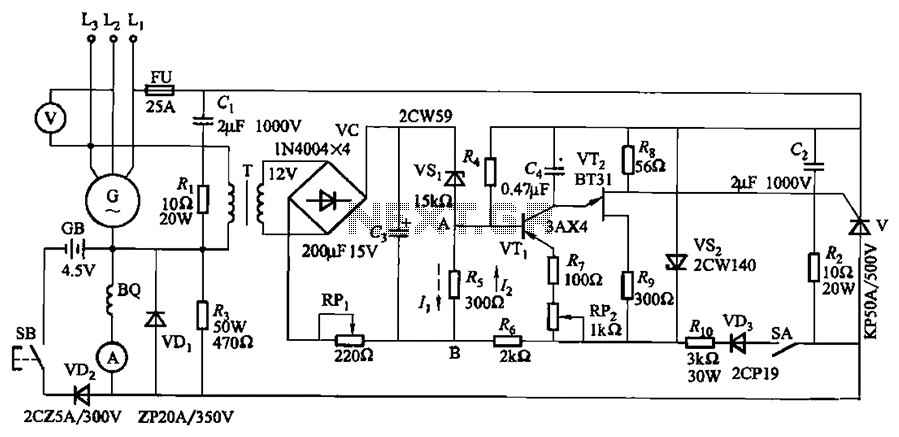
The circuit depicted in Figure 7-32 is designed for an excitation device capable of handling a terminal voltage of 400V and a capacity of less than 75kW for synchronous generator motors, enabling automatic adjustment of excitation. When the generator...
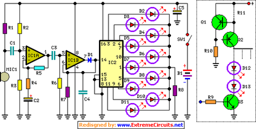
The basic circuit illuminates up to ten LEDs in sequence, following the rhythm of music or speech picked up by a small microphone. The expanded version can drive up to ten strips, each formed by up to five LEDs,...
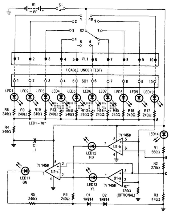
The cable tester utilizes two operational amplifiers (op-amps) configured as window comparators to detect short or open circuit conditions. A third op-amp comparator is employed to indicate a properly functioning circuit, meaning it is neither open nor shorted. Colored...
The FM demodulator circuit, as illustrated in the figure, utilizes a 4046 Phase-Locked Loop (PLL) integrated circuit to convert the intermediate frequency FM input signal into a lower frequency output. The FM demodulator circuit based on the 4046 PLL IC...
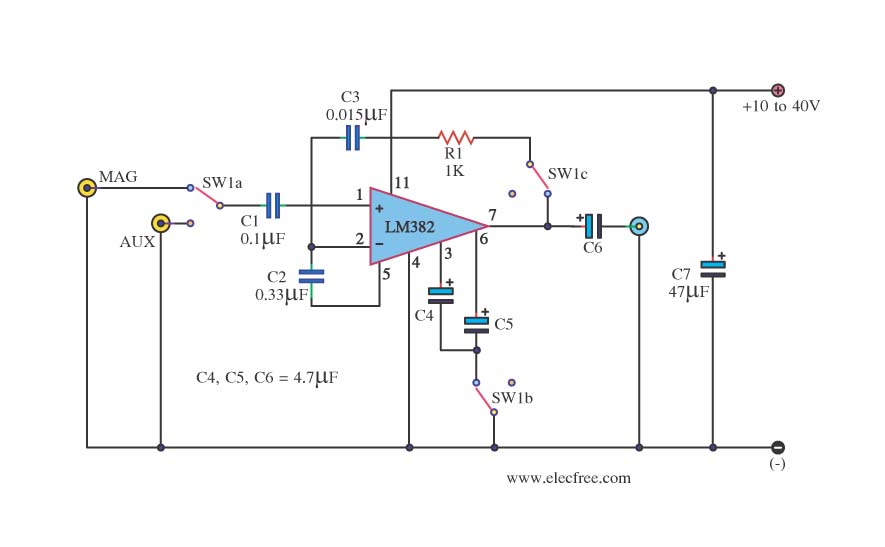
This is a simple preamplifier circuit. It can accept a general AUX sound signal as well as a signal from a microphone. The purpose of the circuit is to amplify the sound signal at the initial stage using an...
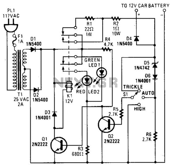
The circuit is capable of supplying either a trickle charge (50 mA) or a high-current charge (1 A). Users can select either charging method or an automatic mode that initially trickle charges a battery if it is particularly low...