
PIC Programmer II
The circuit described operates as a charge pump, utilizing a capacitor (C1) to double the voltage supplied to the system. The operation begins when the TxD line transitions to a negative voltage, allowing C1 to charge through diode D7 from the ground reference. Upon activation of the TxD line to a positive state, the voltage stored in C1 is elevated, effectively doubling the input voltage. The output from the charge pump is then regulated to approximately 13V by D7, ensuring stable operation of the connected circuitry.
The circuit also incorporates additional components such as capacitors (C2) and resistors (R4, R3) to manage the voltage supply (VDD) and its timing. The charge pump's output is delayed via C2 and R4, ensuring that the voltage is stable before being applied to the load. The use of clump diodes (D1-D5) is critical in this design, as they rectify the voltage with minimal forward voltage drop, allowing for efficient operation. The suggested diodes, including 1N4148 and others, are suitable for this application due to their small size and capability to handle the expected current levels.
In scenarios where the connected device, such as the 16F84A, requires higher programming currents, the resistor R3 should be adjusted to a lower value, potentially utilizing a trimmer resistor for fine-tuning. This adjustment is crucial for ensuring reliable operation during programming sessions.
The RCD Programmer's design also considers the potential issues associated with hot plugging into a COM port. To mitigate inrush current that can occur during this operation, a 200-ohm current-limiting resistor is introduced. This component serves to protect the internal circuitry of computers that may not have robust surge protection, although it may result in insufficient voltage levels for proper operation with certain computers.
The overall design emphasizes the importance of voltage regulation and current management in ensuring the stable functionality of the RCD Programmer, particularly in light of newer low-pin-count PIC devices with increased memory capabilities. Adjustments to component values, especially the capacitance of C1, are recommended to enhance programming stability.C1 is a charge pump capacitor*. This works voltage doubler. When TxD is negative voltage, C1 is charged through D7 from GND. If TxD carries out turn-on, since it will become positive voltage, the voltage charged in C1 is raised. The created high voltage is regulated by D7 to about 13V. If TxD carries out turn-on, both supply voltage will be created. CTS and RTS also join creation of supply voltage. This VDD is delayed and is applied by C2 and R4. D1-D5 are clump diodes. Since voltage drop is within the limits which can be disregarded, general purpose small rectifier is sufficient as the diode to be used.
e.g. 1N4148,1S1588(Toshiba),1S2076A(Renesas or Hitachi),1S133(ROHM) . When not succeeding by the device which needs programming current like 16F84(A), the value of R3 is made small. Probably, it will be good using a trimmer resistor as R3. After I published the RCD Programmer on my Web site, it has passed in one year. I obtained various questions about the RCD Programmer from many people. And Microchip newly developed Low-Pincount PICs which built in the memory exceeding 1k words. I recommend change capacity of C1 to 470uF now for stable programming. When you insert a RCD Programmer into the COM port of your computer during operation("Hot Plug-in" or "Hot Socketing"), inrush current is generated. It seems that it is weak to an overcurrent and a short circuit although "EIA/TIA -562" is power saving and compatible with "EIA/TIA-232-E." So, I added 200-ohm current limitation resistor.
This resistor limits peak current and help computers which have poor surge protection circuit inside. However, the RCD programmer will not work well as for such a computer because the voltage of the COM port might be very low.
*About general description of charge pump, please refer to DC/DC Conversion without Inductors(Maxim/Dallas Application Note 725). A important point is not a charge pump but controll of VDD in the RCD Programmer circuit. If this point is excluded, the JDM Programmer is far more excellent than the RCD Programmer. Because the RCD Programmer works by the pulse only once, the capacitor power cannot be continued for a long time.
🔗 External reference
Related Circuits
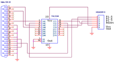
This circuit is designed for use with ATMEL Microcontroller ICs, specifically the AT89Sxx and ATMEGA series. It operates using the MISO, MOSI, SCK, and RESET signals. This circuit serves as a foundational interface for programming and communication with ATMEL microcontrollers,...
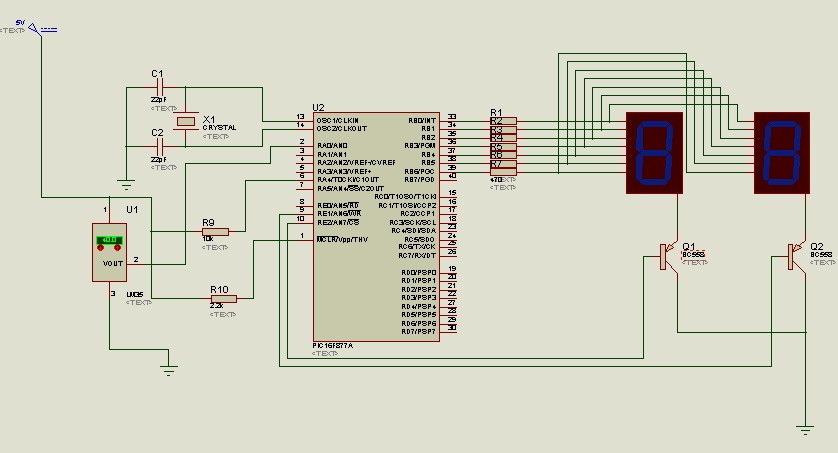
The circuit utilizes the LM35 temperature sensor to measure temperature in the range of 0 to 99 degrees Celsius and displays the readings using two seven-segment displays. It is designed to activate devices through the RC pins; for instance,...
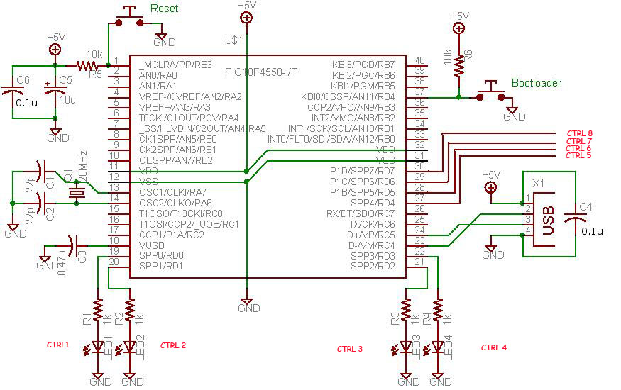
This project demonstrates a computer control interface using a USB board (USB Interface Project). This tutorial provides a straightforward method to control devices such as LEDs, motors, and other components via a computer using a USB board. Traditionally, devices...
Our present car controller runs on a single PIC16F870 micro and provides functions for remote door locks, headlight reminder, and car finder. It is constructed using wire-wrap to allow for future expansion and is mounted using Velcro on the...
This device uses a PIC12F615 to implement a capacitor discharge ignition system. When the switch (button) is closed, the PIC sends pulses to the IRF644 MosFet creating high voltage pulses to charge the 1.0 uf/250 volt capacitor. The voltage...
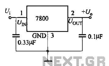
A fixed three-terminal integrated voltage regulator can be directly employed in various electronic devices as a voltage regulator. It features internal protections such as overcurrent protection, thermal protection, and safe operating area protection, making the circuit easy to use,...