
pic thermometer
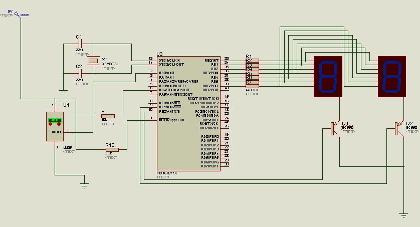
The circuit design primarily revolves around the LM35 temperature sensor, which provides an analog output that is directly proportional to the temperature in degrees Celsius. The output voltage from the LM35 is typically 10 mV per degree Celsius, allowing for straightforward interfacing with an analog-to-digital converter (ADC) or a microcontroller with ADC capabilities.
In this configuration, the microcontroller receives the analog voltage from the LM35 and processes it to determine the corresponding temperature. The temperature value is then displayed on two seven-segment displays. The choice of using two displays limits the output to integer values ranging from 0 to 99 degrees Celsius, simplifying the design while still meeting basic temperature monitoring needs.
The activation of devices via the RC pins is an essential feature of the circuit. When the temperature exceeds a predetermined threshold of 39 degrees Celsius, the microcontroller sends a signal to the RC0 pin, which can be connected to a relay or a transistor to control higher power devices, such as a fan. This functionality enables automatic cooling based on temperature readings, enhancing user convenience and energy efficiency.
The original circuit's complexity was reduced by eliminating one temperature sensor and one display. While the more complex design could provide decimal precision, the two-display configuration suffices for applications where precise decimal readings are not critical. The modifications made were based on simulation results that indicated discrepancies in output, prompting a design that would yield reliable performance in practical applications.
The microcontroller's programming aspect is crucial for the circuit's operation. Although the microcontroller has not been programmed in this instance, the HEX file available from the source site can be utilized to load the necessary firmware. This firmware typically includes the logic for reading the temperature, converting it to a digital format, controlling the display outputs, and managing the device activation through the RC pins.
Overall, this circuit represents a practical approach to temperature monitoring and control, suitable for various applications where temperature regulation is essential. The design balances simplicity and functionality, ensuring reliable operation while facilitating easy implementation.The circuit uses LM35 as its temperature sensor, and displays the temperature (0-99 Celsius) using the two 7 segment display. The circuit is also programmed to turn on devices using the RC pins. Example: RC0 is ON when the temperature is above 39 Celsius. One application is to turn on a fan whe n it is already too hot. That`s why we included additional circuit for this application Original circuit from HAMRADIOINDIA. The circuit there uses two temperature sensors and 3 seven segment displays because of decimal point in the output (e. g. 25. 6 Celsius). I modified the circuit and simplified it by removing the spare sensor and using only two display. The reason is when I simulated it in Proteus, the output is somehow wrong. I don`t know if the output is right on actual but since I want to make sure with the actual circuit, I followed my schematic that gives the right output on simulation.
I did not program the microcontroller. The HEX is from the site and the code is available there. 🔗 External reference
Related Circuits

A horn driver project developed by Microchip Technology is illustrated in this circuit diagram. This horn driver project utilizes the PIC16F886 microcontroller from Microchip. The circuit diagram for the PIC microcontroller horn driver is straightforward and requires minimal external...

A remote sensor transmits data through the mains supply, with a temperature range of 00.0 to 99.9 °C. This circuit is designed for precise centigrade temperature measurement. The circuit employs a remote temperature sensor that communicates its readings over the...
In the present day, a wide variety of sensors are available to measure almost anything. This tutorial will explore the fascinating world of sensors, starting with a very simple analog temperature sensor, the LM35. The process of interfacing it...

This preamplifier offers a loading ratio of better than -70 dB (referenced to a 10-ohm reluctance phono cartridge) and accepts millivolt input at 1 kHz. It has a dynamic range of approximately 35 dB of gain at 1 kHz...
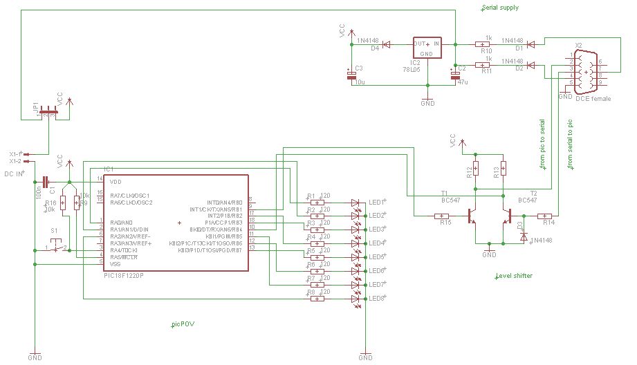
PicPOV is a project based on "persistence of vision." A PIC microcontroller blinks 8 LEDs on and off so that when waved through the air, a message is displayed. The PicPOV project utilizes the principle of persistence of vision to...

A simple operational amplifier and silicon diode form the core of a temperature-to-voltage converter, which allows the use of a standard voltmeter—either analog or digital—to measure temperature. User adjustments enable readings of either 10 mV or 100 mV to...