
PIC16F886 Based Horn Driver ECE Mini Project
The horn driver circuit based on the PIC16F886 microcontroller is designed for efficient control of horn actuators through precise PWM signal generation. The ECCP module's Half-Bridge mode is particularly effective for driving inductive loads such as horns, allowing for effective control of the voltage and current supplied to the horn. The integration of an ADC input enables real-time monitoring of the horn's performance, facilitating feedback control mechanisms that can adjust the PWM parameters based on the horn's response.
The circuit's design emphasizes simplicity, requiring only essential external components, which enhances reliability and reduces overall system complexity. The use of the internal 8 MHz oscillator simplifies the design by eliminating the need for an external clock source, while the Timer2 functionality allows for accurate timing control necessary for PWM signal generation.
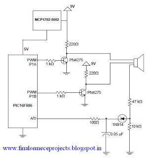
The prescaling mechanism ensures that the PWM frequency remains within the operational limits of the Timer2, providing a range of output frequencies suitable for various horn types. The ability to adjust the duty cycle to 50% ensures that the horn receives adequate power for optimal performance without overheating or damaging the components. This project exemplifies an effective application of microcontroller technology in automotive or industrial horn activation systems, showcasing the capabilities of the PIC16F886 in real-world applications.A very interesting horn driver project presented by Microchip technology is presented in this circuit diagram. This horn driver project is based on PIC16F886 microcontroller, from Microchip. This microcontroller horn driver circuit diagram is very simple and require few external components. The PIC MCU has peripheral resources within the devic e to provide horn driver services in a very simple manner. The PIC MCU peripherals include the Enhanced CCP (ECCP) module in Pulse-Width Modulation (PWM) Half-Bridge mode to drive the 2 horn drive leads and a single ADC input to monitor the horn feedback after it has been conditioned. Horn characteristics are required to determine the defined parameters for the range of the PWM module.
For example, a horn with a resonant frequency of 3. 5 kHz ± 0. 5 kHz; the PWM module generates a PWM frequency output from 3 kHz to 4 kHz with 50% duty cycle. With a device that is running off of the internal oscillator at 8 MHz, the clock source to Timer2 that drives the PWM period generates 2M clocks per second. For a 3 kHz period, this is 667 clocks per cycle, and for a 4 kHz period, this is 500 clocks per cycle.
Because Timer2 is an 8-bit timer, accepting only a maximum value of 255, these clocks per cycle must be divided (a prescaler of divide-by-4, yielding 166 clocks per cycle for 3 kHz, and 125 clocks per cycle for 4 kHz). The PWM output driven by the ECCP module in Half-Bridge mode, with both the P1A and P1B outputs active-high, will step through the 125 through 166 clocks per cycle periods at a period rate, and as the Period register is loaded, the value will be dividedby- 2 and loaded into the Duty Cycle register for a 50% duty cycle.
This will become the new PWM period for measuring the feedback from the horn driver, and drives the transistor that raises the level that the horn lead sees, to 9V. 🔗 External reference
Related Circuits
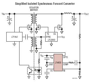
The LT4430 drives the opto-coupler that crosses the galvanic barrier in an isolated power supply. The IC contains a precision-trimmed reference, a high bandwidth error amplifier, an inverting gain of 6 stage to drive the opto-coupler, and unique overshoot...
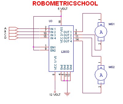
The electronic schematic of a DC motor driver using the L293D, as illustrated in Figure 2, enables the control of two DC motors continuously. It allows for one motor to rotate clockwise while the other rotates counterclockwise. Additionally, all...
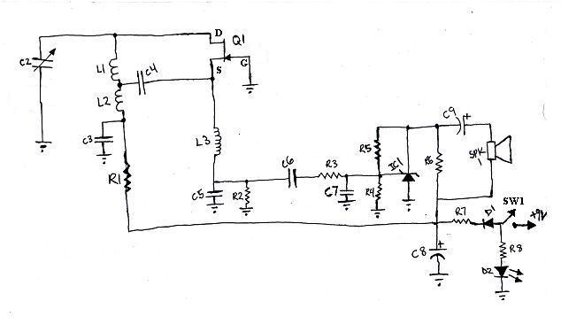
L1 and L2 were constructed by wrapping three tight loops side by side around a Sharpie marker. L2 was additionally created by wrapping approximately 8 inches of 35 AWG magnet wire around a ferrite core, ensuring that the windings...
This circuit is a mini bicycle bell. The mini bicycle bell is activated by a switch that functions as a button. When the button is pressed, an electric current flows through a 9V electronic circuit via the transistor Q1....
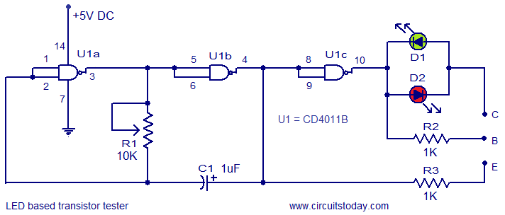
This circuit represents a simple transistor tester that utilizes two LEDs to indicate the condition of a transistor. It is capable of testing both PNP and NPN transistors. The core component of the circuit is the quad 2-input CMOS...
Gates U1-a and U1-b of the 4093 quad 2-input NAND Schmitt trigger are connected in variable, low-frequency square-wave oscillator circuits. The output of gate U1-a is connected to one of the inputs of gate U1-b. The square-wave output of...
Warning: include(partials/cookie-banner.php): Failed to open stream: Permission denied in /var/www/html/nextgr/view-circuit.php on line 713
Warning: include(): Failed opening 'partials/cookie-banner.php' for inclusion (include_path='.:/usr/share/php') in /var/www/html/nextgr/view-circuit.php on line 713