
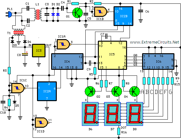
PIC16F628 as digital Tachometer
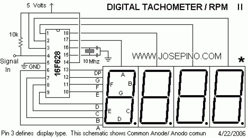
The circuit described involves a microcontroller interface designed to work with a 7-segment LED display for RPM (revolutions per minute) indication. Pin 3 of the microcontroller is pivotal as it determines the type of display being used. For a common cathode configuration, this pin should be connected to ground, allowing the segments of the display to light up when the corresponding control signals are activated. Conversely, for a common anode configuration, Pin 3 must be connected to the positive voltage supply (VCC), enabling the segments to illuminate when the control signals are pulled to ground.
Pin 4 serves as the signal input, which is critical for capturing the RPM data from various sensors. Suitable sensors include optical sensors, such as phototransistors and photoresistors, as well as magnetic sensors like Hall effect sensors and reed switches. It is essential to avoid connecting any high-voltage signals directly to Pin 4, as this could potentially damage the microcontroller. If the input signal exceeds 5 volts, a signal conditioning method should be employed, utilizing drivers such as TTL or CMOS logic, operational amplifiers, or transistors to ensure that the microcontroller receives safe voltage levels.
For optimal performance, the circuit requires a 10MHz crystal oscillator paired with capacitors rated at either 22pF or 33pF to stabilize the clock signal. This setup is crucial for accurate timing and processing of the RPM readings. The design includes a faster sampling rate compared to previous versions, which enhances the responsiveness of the display, providing real-time RPM readings based on the input signal detected at Pin 4. This ensures that users receive immediate feedback regarding the operational speed of the monitored system, which is particularly beneficial in automotive applications.Pin 3 defines the Display type: Common Cathode or Common Anode. Connect this pin to GROUND if you are using common cathode 7-segment led displays. To use common anode displays, connect it to VCC (positive) Pin 4 is the signal input, you can use optical sensors (Fototransistors, fotoresistors, etc), magnetic sensors (Hall effect, reed switch, etc) or using a switch. Unfortunately, I have no idea how to connect this circuit to a vehicle. If you want to share details about how to attach this circuit to an automovile, I will post this information.
DO NOT CONNECT ANY SIGNAL DIRECTLY TO PIN 4. High voltages can damage the PIC. If the input signal is more than 5 Volts, Use a driver as TTL, CMOS, Amp Operational or Transistors. NOTE: Use only 10Mhz xtal and 22pf or 33pf capacitors. The RPM are displayed as units, that means, the RPM indicated in the display is the actual reading from the input pin. This version have a faster sample rate so the reading is constantly updated, you get a faster reading that the previous version.
🔗 External reference
Related Circuits
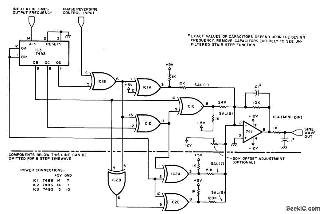
A sine-wave generator produces a Walsh-function approximation of the sine function. The frequency of the sine wave is determined by a square-wave input to pin 14 of a 7493 integrated circuit. Filter components of the operational amplifier assist in...
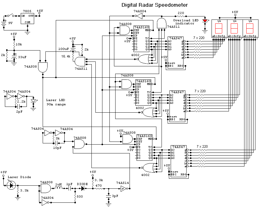
This circuit is a Digital Radar Speedometer. It allows the evaluation of the speed of any moving object, particularly cars and other vehicles. The speed is measured in kilometers per hour (KPH) and is displayed using a three-digit format....

A remote sensor transmits data through the mains supply, with a temperature range of 00.0 to 99.9 °C. This circuit is designed for precise centigrade temperature measurement. The circuit employs a remote temperature sensor that communicates its readings over the...

The circuit described is a crystal oscillation circuit using a CM OS inverting configuration, designed to ensure accurate operation. It employs a BCD counter (IC2) capable of achieving a maximum oscillation frequency of 2 MHz, which is 100 times...
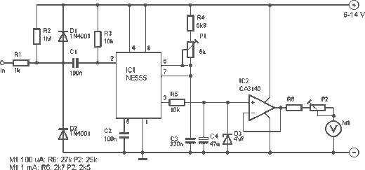
This is a nice design for people who have no tachometer in the car or on the bike. The circuit uses two ICs: an NE 555 and a CA 3140. The input of the circuit is connected to the...
This circuit is designed for precise measurement of temperature in degrees Celsius. It includes a transmitter section that converts the output voltage from the sensor, which is proportional to the temperature being measured, into a frequency signal. This frequency...
Warning: include(partials/cookie-banner.php): Failed to open stream: Permission denied in /var/www/html/nextgr/view-circuit.php on line 713
Warning: include(): Failed opening 'partials/cookie-banner.php' for inclusion (include_path='.:/usr/share/php') in /var/www/html/nextgr/view-circuit.php on line 713