
pic16f877 based simple calculator project
The PIC16F877 microcontroller is a versatile and widely used device in embedded systems, particularly for educational purposes and simple applications. The described implementation focuses on creating a basic one-digit calculator that can perform fundamental arithmetic operations such as addition, subtraction, multiplication, and division.
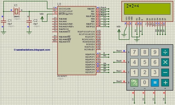
The schematic for the one-digit calculator would typically include the PIC16F877 microcontroller connected to a seven-segment display for output, a keypad for input, and necessary supporting components such as resistors and capacitors. The keypad can be a 4x4 matrix configuration, allowing users to input numbers (0-9) and operations (+, -, *, /).
The microcontroller's I/O pins are configured to read the keypad inputs and display the results on the seven-segment display. The firmware programmed into the PIC16F877 handles the logic for performing calculations based on the user's input. It would include a simple state machine to manage the operations and transitions between input states.
Power supply considerations for the circuit should include a regulated voltage source, typically 5V, to ensure stable operation of the microcontroller and connected components. Bypass capacitors should be placed close to the power pins of the microcontroller to filter out noise and stabilize the power supply.
Overall, this implementation serves as an excellent example of utilizing a microcontroller to perform basic arithmetic functions while providing hands-on experience with embedded programming and circuit design.This PIC microcontroller tutorial provides a simple calculator implementation for PIC16F877 microcontroller. This is a simple one digit calculator which im.. 🔗 External reference
Related Circuits
Trimming is straightforward when matched NPN transistors are utilized for Q1 and Q2, along with 1% tolerance resistors for R6 to R11. A dual trace oscilloscope, digital voltmeter (DVM), and sine wave generator are required for this process. Although...
This temperature switch utilizes several discrete components to activate a buzzer when the ambient temperature rises. It is suitable for use as a straightforward fire alarm indicator. The temperature switch circuit is designed to monitor environmental temperature changes and provide...
The circuit diagram presented is for a compact mini audio power amplifier that operates with a DC supply voltage ranging from 4.5 volts to a maximum of 18 volts. This amplifier utilizes the TDA1015 integrated circuit, produced by NXP...
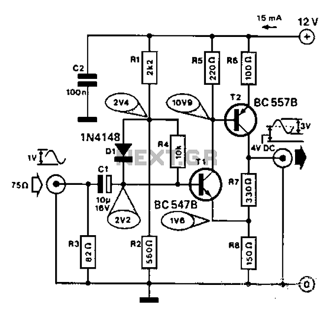
Commonly used for cameras or computers with black and white television connections, the amplifier has a gain of 3 and a bandwidth of 10 MHz. The described circuit is an amplifier designed for applications involving cameras or computers that interface...

This is the simplest single transistor FM wireless transmitter circuit ever posted in CircuitsGallery. In the field of telecommunications, frequency modulation (FM) transmits information by altering the frequency of a carrier wave based on the message signal. FM utilizes...

The loop antenna L1 is utilized for emission and also functions as the oscillation coil. The high-frequency current flowing through the antenna is synchronized in resonance with the oscillation frequency, ensuring optimal emission performance. Practical applications indicate that the...
Warning: include(partials/cookie-banner.php): Failed to open stream: Permission denied in /var/www/html/nextgr/view-circuit.php on line 713
Warning: include(): Failed opening 'partials/cookie-banner.php' for inclusion (include_path='.:/usr/share/php') in /var/www/html/nextgr/view-circuit.php on line 713