
PICAXE LCD Thermometer

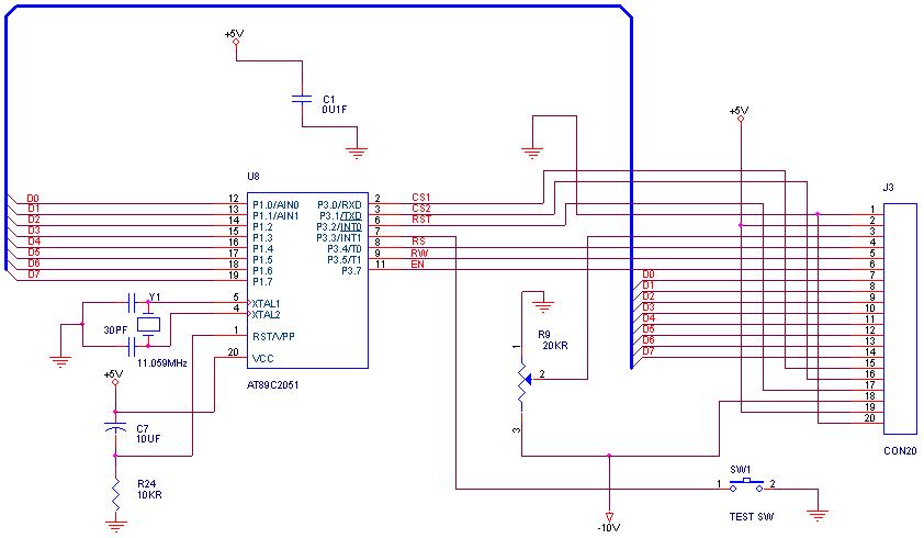
The circuit utilizes a DS18B20 temperature sensor connected to the PICAXE 28X1 microcontroller. The sensor communicates via a one-wire protocol, providing temperature readings that are processed by the microcontroller. The temperature is measured in a 16-bit format, allowing for precise readings. The microcontroller's variables are used to store the temperature values, limits, and control signals for the output.
The LCD display is initialized and controlled through specific pins on the microcontroller, allowing for real-time temperature readings to be shown. The system checks the measured temperature against defined upper (TH) and lower (TL) limits. If the temperature is below the upper limit, an output pin is set high, indicating a safe temperature range, while if the temperature exceeds the lower limit, the output pin is set low, signaling an alert condition.
The serial communication is established through the RS-232 interface, enabling the microcontroller to send temperature data to an external terminal. This feature provides an additional layer of monitoring, allowing the user to observe temperature trends over time.
The program structure includes initialization routines, a main loop for continuous operation, and subroutines for temperature measurement, limit checking, data sending, and display updating. The use of EEPROM for storing the greeting message ensures that the system retains this information even after power loss. Overall, this circuit provides a comprehensive solution for temperature monitoring and control, suitable for various applications, including environmental monitoring and industrial processes.Measures the temperature with DS18B20 temp. sensor and shows on the 2x16 char LCD display, also sends to the serial terminal, and checks against the limits and sets the output accordingly high if temp is lower then higher limit low if temp is higher then lower limit. picaxe28x1 variables bit0-31, b0-27, w0-13 variables used here: symbol lcdchar = b4 symbol lcdtmp = b5 symbol counter = b6 symbol position = b7 symbol tenths = b8 symbol ones = b9 ; 16-bit measured temperature symbol temp12 = w5 symbol temp12lo = b10 symbol temp12hi = b11 ; 16-bit lower temp.
limit symbol TL = w6 symbol TLlo = b12 symbol TLhi = b13 ; 16-bit higher temp. limit symbol TH = w7 symbol THlo = b14 symbol THhi = b15 ; status of the output pin symbol LED = bit0 ; greetings message eeprom 0, ("GPtronics 2010Thermometer") #rem here is the table for decimal part of the temp reading first measuring to determine initial status of the output relay gosub init gosub lcdinit ; initialization of the lcd display gosub hello ; greeting message - just for fun :) main2: ; loop gosub taketemp ; temperature measuring gosub checklimits ; checks measured temp. against limits and sets output accordingly gosub sendtemp ; sends data to rs-232 gosub showtemp ; converts numbers and shows them on lcd goto main2 ; loop again ; = init: counter = 0 TLhi = 22 ; lower temperature limit TLlo = 0 THhi = 24 ; higher temperature limit THlo = 0 if temp12 <= TH then : gosub ledon : else : gosub ledoff : endif return ; = lcdinit: pins = 0 pause 200 pins = 48 gosub pulsing gosub pulsing gosub pulsing pins = 32 gosub pulsing gosub pulsing pins = 128 gosub pulsing lcdchar = 14 gosub wrins lcdchar = 12 gosub wrins return pulsing: pulsout 3, 3 pause 10 return ; = wrchr: pins = lcdchar & 240 high 2 pulsout 3, 1 lcdtmp = lcdchar * 16 pins = lcdtmp & 240 high 2 pulsout 3, 1 return wrins: pins = lcdchar & 240 pulsout 3, 1 lcdtmp = lcdchar *16 pins = lcdtmp & 240 pulsout 3, 1 high 2 return ; = hello: lcdchar = 1 gosub wrins lcdchar = 12 gosub wrins for counter = 0 to 13 read counter, lcdchar gosub wrchr next counter lcdchar = 192 gosub wrins for counter = 14 to 24 read counter, lcdchar gosub wrchr next counter pause 1000 lcdchar = 1 gosub wrins return ; = taketemp: readtemp12 7, temp12 temp12 = temp12 * 16 temp12lo = temp12lo / 16 return ; = sendtemp: #rem sertxd("Temp= ", #temp12hi, " and ", #temp12lo, "/16 C", 13, 10) sertxd("TH= ", #THhi, " and ", #THlo, "/16 C", 13, 10) sertxd("TL= ", #TLhi, " and ", #TLlo, "/16 C", 13, 10) return #endrem sertxd("Temp= ", #temp12, 13, 10) sertxd("TH= ", #TH, 13, 10) sertxd("TL= ", #TL, 13, 10) return ; = showtemp: lcdchar = 2 gosub wrins lcdchar = temp12hi / 100 if lcdchar = 0 then leadzero lcdchar = lcdchar + 48 goto nonleadzero leadzero: lcdchar = lcdchar + 32 nonleadzero: tenths = temp12hi // 100 gosub wrchr ; write 100s lcdchar = tenths / 1
🔗 External reference
Related Circuits

When the system is placed in a shop or mall, logos and product advertisements serve as an ideal complement to temperature information. For home use, photographs of children at the beach or, should the temperature drop, images of making...
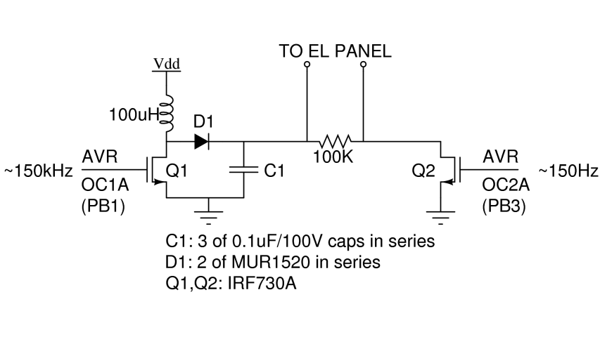
There are two primary types of backlights for LCDs: LEDs, which stands for light-emitting diodes, and EL, which stands for electroluminescent. EL backlights are generally more efficient and provide more uniform lighting compared to LED backlights, but they require...
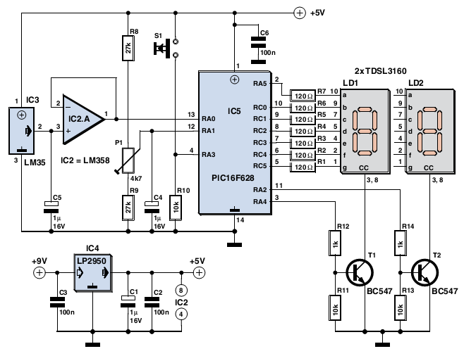
The device is user-friendly and consumes minimal current, allowing it to operate throughout the battery's shelf life. It employs a standard LM35DZ sensor (IC3) whose analog output voltage is buffered by an LM358 (IC2A). The voltage is processed by...
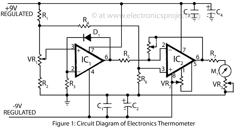
A clinical thermometer is typically used by doctors due to its complex reading mechanism. This circuit represents an electronic thermometer designed to measure a wide temperature range from -200°C to 1250°C. This single circuit electronic thermometer is capable of...
Research has been conducted on a project aimed at enhancing understanding of electronics, networking, and programming. The project involves the construction of an online thermometer suitable for applications requiring temperature monitoring. The current work environment is a laboratory where...
How can graphical LCDs be controlled using a microcontroller? Is there any datasheet available? Graphical LCDs (Liquid Crystal Displays) are widely used in various electronic applications for displaying complex graphics and text. To control these displays with a microcontroller, several...