
White LED Lights Circuit

The LED floodlight circuit typically consists of a power supply, a control circuit, and the LED array itself. The power supply can be either an AC to DC converter or a direct DC power source, depending on the application. For a standard LED floodlight, a switching power supply is often used to efficiently convert the input voltage to the required operating voltage for the LEDs.
The control circuit is responsible for regulating the current flowing through the LED array to ensure optimal brightness and longevity of the LEDs. This may include components such as resistors, capacitors, and sometimes a microcontroller for more advanced features like dimming or color temperature adjustment.
The LED array is composed of multiple white LEDs arranged in a manner that provides uniform illumination across the desired area. The use of a heat sink is crucial in this design, as it dissipates heat generated by the LEDs during operation, thereby preventing thermal runaway and prolonging the lifespan of the floodlight.
Overall, the simplicity of the circuit design contributes to the energy efficiency of the floodlight, making it an ideal choice for outdoor lighting applications. The cool white light emitted by the LEDs enhances visibility while providing a modern aesthetic to outdoor spaces.This white LED flood lights illuminates your porch with cool white light. The circuit is too simple and energy saving design. Its current consumption is pr.. 🔗 External reference
Related Circuits
Some simple 555 and flip-flop circuits are being developed to add electronic lighting effects to modernize games. Various circuits are being collected for different game aspects, such as idle states, flipper shots, flower openings, winning shots, etc. A collection...
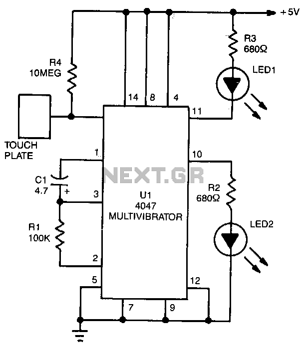
LED1 and LED2 indicators activate and stay illuminated each time the circuit is triggered. During the timing cycle, the Q output at pin 10 of U1 becomes positive when the Q output at pin 11 turns negative. The two...
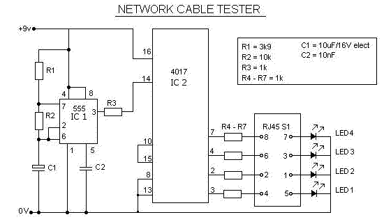
This is a multifunction RJ45 network cable tester designed for testing network cables (RJ45) and telephone cables (RJ11). It is cost-effective and user-friendly. The tester determines whether a network cable is a crossover or straight type by illuminating a...

This panning circuit, also known as a panoramic control circuit, allows for the adjustment of the perceived position of a microphone's input across two output channels. This effect is frequently utilized in mixing consoles within recording studios. Panning enables...
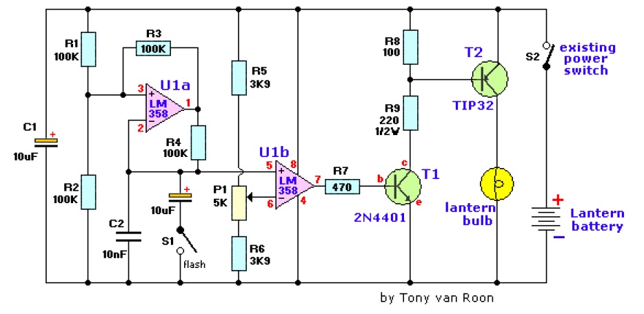
The electronic lantern control circuit enhances an existing battery-powered lantern or flashlight, or can be incorporated into a custom design, by providing high-efficiency dimming and flashing capabilities. This circuit is particularly useful in automotive applications, serving as an effective...

The circuit depicted utilizes the UPC1651 integrated circuit produced by NEC Corporation of Japan. It offers high gain and stability, ensuring optimal performance for microphones. The design incorporates an FM transmitter circuit. The system employs a flexible antenna measuring...
Warning: include(partials/cookie-banner.php): Failed to open stream: Permission denied in /var/www/html/nextgr/view-circuit.php on line 713
Warning: include(): Failed opening 'partials/cookie-banner.php' for inclusion (include_path='.:/usr/share/php') in /var/www/html/nextgr/view-circuit.php on line 713