
PIR Sensor Circuits
The circuit design for a 12 Volt DC powered PIR sensor system involves several key components and connections. The primary component, the Honeywell IS-215T PIR sensor, operates on a low current consumption, making it ideal for renewable energy applications. The sensor's terminal strip allows for easy connections, with the + and - terminals connecting to the power supply and the C and NC terminals interfacing with the internal relay.
The relay's operation is crucial for the alarm system's effectiveness. When the PIR sensor does not detect motion, the relay remains open, allowing the Common (C) and Normally Closed (NC) terminals to be shorted, producing a continuous high signal at the NC terminal. This signal can trigger an alarm or alert system. Conversely, when motion is detected, the relay closes, interrupting the connection between C and NC, resulting in the cessation of the high signal, which effectively alerts the alarm system to potential intrusions.
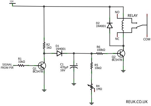
To adapt the output of the PIR sensor for various applications, a logic NOT gate can be implemented using an NPN transistor. This configuration allows for the inversion of the PIR sensor's output. The output from the NOT gate can be utilized to control additional components, such as a relay or LED spotlight, enhancing the versatility of the system. The transistor inverter circuit consists of a few resistors and an NPN transistor, which together facilitate the desired output inversion.
In summary, this 12 Volt DC powered PIR sensor system provides a robust solution for motion detection applications, particularly in renewable energy scenarios. The design ensures reliable operation, with built-in safeguards against tampering, while offering flexibility for various output configurations to suit different security and lighting needs.Of particular interest to us are 12 Volt DC powered PIR sensors and associated circuits since these can be powered directly from a 12 Volt battery which is in turn charged by wind, solar, or other renewable energy sources. In this article we will look at the ways in which the excellent low current consumption Honeywell IS-215T* 12 Volt DC PIR sensor (available in the REUK Shop ) can be
used by the renewable energy enthusiast for lighting, security, and other motion detection systems. There are many other home security PIR sensors from other manufacturers which have the same mode of operation as the Honeywell unit, so the following circuits and details will still be applicable with those. When the cover of the PIR Sensor unit is popped off it appears as shown below. A row of terminal strip at the top right of the circuit board is used for making the necessary connections - two connections to provide power to the unit (labelled + and -) and two for the internal relay (labelled C and NC).
The `C` is short for Common, and the `NC` for Normally Closed. The most important thing to note about the vast majority of home alarm system PIR sensors is that they output a HIGH signal when motion is NOT being detected, and no signal at all when it IS being detected. Why are they designed this way Because if there was no signal at all when motion was not being detected, a burglar could simply cut the cables leading into the security alarm controller, and then when the signals went high when a PIR detected motion, the controller would not receive those signals and the alarm would not be triggered.
With a high signal when motion is not detected, if any cables are cut or if motion is detected no signal will get to the controller and the alarm will be triggered immediately. The `C` and `NC` screw-in terminals on the PIR sensor are connected to the terminals of an internal relay, and the positive of the 12V power supply is connected to the `C` terminal.
While motion is not being detected (or if a burglar cuts the power to it), the PIR sensor leaves the relay open meaning that `C` and `NC` are internally connected to one another (shorted). Therefore a high signal (positive 12V) comes out of the `NC` terminal which is then connected to the alarm system (or used in your motion sensing application).
When motion is detected, the relay is closed, `C` and `NC` are no longer shorted, and so the positive 12V from `C` is no longer outputted from `NC`. PIR modules designed for use in other non-security applications (such as the KC7783R PIR module are designed to output a high signal when motion IS detected and no signal or 0V when it is not.
This makes it simpler to sound a buzzer when motion is detected for example. In order to get a more useful high signal when motion is detected we need to invert the output from the PIR sensor. For this we need a logic NOT gate - a device which will output a low signal when the input is high, and output a high signal when the input is low.
This can easily be achieved by making a simple transistor inverter NOT gate with an NPN transistor and a couple of resistors as shown below. So, when the PIR sensor unit detects motion, the LED on the PIR sensor lights up, there is no PIR Sensor signal (low) so that is inverted to an output signal of +12V (by our simple NOT gate).
When no motion is detected, the LED is not lit, the PIR sensor signal is +12V which is then inverted to an output signal of 0V (low). The output signal can then be connected to the base of another transistor which can in turn pass current across the coil of a relay, light up a 12 Volt LED spotlight, or power a buzzer/alarm as shown below.
There is however one problem. The device (or circuit) connected to the output from the NOT gate inverting circuit will only receive the high signal for as lon 🔗 External reference
Related Circuits
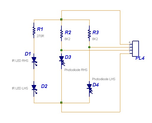
The following circuit illustrates a Line Follower Sensor Circuit Diagram. Features include a simple design, with Infrared LEDs D1 and D2 emitting infrared light. The Line Follower Sensor Circuit is designed to detect the presence of a line, typically a...
Install the PIR module hanging from a 3-meter high mast to cover a 10-meter radius area. Connect its supply and relay terminals to the finished and enclosed circuit, ensuring the correct polarity is observed. A 4-core screened cable can...
This is a pressure sensor signal conditioning circuit. It is a simple and inexpensive circuit due to its small geometry and the use of a straightforward pressure sensor. The pressure sensor signal conditioning circuit is designed to convert the raw...
These two projects, Wah and Fuzz, are the results of a modification to a Morley dual channel volume control pedal that one of my sons suggested I undertake as he had no use for the volume unit but thought...
A car inverter, also known as a power converter or power inverter, is a device that converts 12V DC from a vehicle’s electrical system into 220V AC for general electrical use. It serves as a convenient power adapter for...
An opto-interrupter made with Lego beams, regular parts, a 6 hole pulley wheel and an axle. More: I started out with Michael Gasperi's idea with the 6 whole pulley installed in a Lego enclosure with axle and beams so...
Warning: include(partials/cookie-banner.php): Failed to open stream: Permission denied in /var/www/html/nextgr/view-circuit.php on line 713
Warning: include(): Failed opening 'partials/cookie-banner.php' for inclusion (include_path='.:/usr/share/php') in /var/www/html/nextgr/view-circuit.php on line 713