
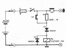
Polarity Reverser

In motor control systems, ensuring that the supply voltage maintains the correct polarity is crucial for the proper operation of the motor. Incorrect polarity can lead to malfunction or damage to the motor, which can be detrimental in applications requiring precise control and reliability.
To achieve this, a circuit design may incorporate a polarity protection mechanism. This can be implemented using various components such as diodes, which allow current to flow in only one direction, thus safeguarding the motor from reverse polarity conditions. A typical configuration might include a bridge rectifier, which can convert alternating current (AC) to direct current (DC) while ensuring that the output voltage maintains the desired polarity regardless of the input conditions.
In addition to diodes, the circuit may also employ relays or MOSFETs to control the direction of current flow. A relay can be used to switch the connections based on control signals, ensuring that the motor receives the correct voltage polarity for forward or reverse operation. MOSFETs, on the other hand, can provide faster switching capabilities and lower on-resistance, improving efficiency in the circuit.
Moreover, integrating a voltage monitoring system can enhance the reliability of the circuit. This system can detect any discrepancies in voltage polarity and provide feedback to a control unit, which can then take corrective action, such as disconnecting the power supply or activating an alarm.
Overall, the design of a motor control circuit that ensures correct voltage polarity involves a combination of protective components, switching devices, and monitoring systems to create a robust and reliable solution for various applications.There are systems in which it is imperative that the supply voltage of, say, a motor, always has the correct polarity. It is, of course, possible to use a.. 🔗 External reference
Related Circuits
This document describes how to construct a dual polarity linear power supply which can be configured for any positive or negative voltage between 1.2-35V. A power supply is the fundamental building block of all but the simplest of electronic...
In a stereo system, it is often important to determine whether the speakers are polarized. This can be especially problematic if the speaker cables lack polarity markings. The circuit described will assist in identifying the correct terminals for the...
Safety polarity connection circuit design using common electronic components The safety polarity connection circuit is designed to ensure that electronic devices are connected with the correct polarity, preventing damage from reversed connections. This circuit typically employs common electronic components such...
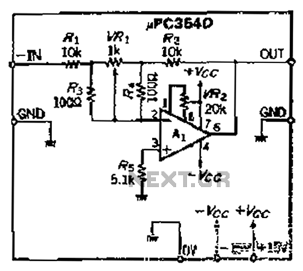
The loop gain of the operational amplifier (OP) is primarily influenced by the ratio of the input resistor to the feedback resistor. Consequently, any resistance error can lead to a corresponding gain error, which necessitates the use of high-precision...
This tester can be used to check the polarity of any power source, and is therefore very useful when installing automotive equipment, alarm systems or anything else you can think of. Because this circuit is so simple and cheap,...
The simplest polarity protection technique is to connect a series diode to the power line input. The diode conducts only when the power supply is connected correctly. A series diode is an effective method for preventing reverse polarity in electronic...