
stepper remote control car
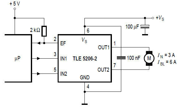
The stepper motor control circuit is designed to manage the operation of a stepper motor, specifically utilizing the TLE5206 integrated circuit. This circuit is particularly suitable for applications in remote control cars, where precise motor control is essential for maneuverability and performance.
The TLE5206 is a dual H-bridge driver that allows for bidirectional control of the stepper motor. It can handle a wide range of supply voltages and provides built-in protection features such as thermal shutdown and overcurrent protection, ensuring reliable operation in varying conditions.
In the schematic, the stepper motor is connected to the outputs of the TLE5206, which are configured to drive the motor phases. The control signals for the TLE5206 can be generated from a microcontroller or a dedicated control circuit, which sends step and direction commands to the driver. The microcontroller typically outputs pulse-width modulation (PWM) signals that dictate the speed and direction of the motor.
Additional components in the circuit may include capacitors for power supply decoupling, resistors for current limiting, and diodes for flyback protection, which safeguard the circuit from voltage spikes caused by the inductive load of the stepper motor. The design should also include provisions for heat dissipation, as the TLE5206 may generate heat during operation, especially under load.
Overall, this stepper motor control circuit is a robust solution for controlling the motion of stepper motors in remote control applications, providing both efficiency and reliability through the use of the TLE5206 driver.Stepper motor control circuit Stepper motor control circuit diagram using TLE5206 for remote control car.. 🔗 External reference
Related Circuits
To create a versatile and generic microcontroller board, the information provided thus far is sufficient. It covers the essential components needed to achieve this. The design of a microcontroller board requires careful consideration of various factors to ensure versatility and...
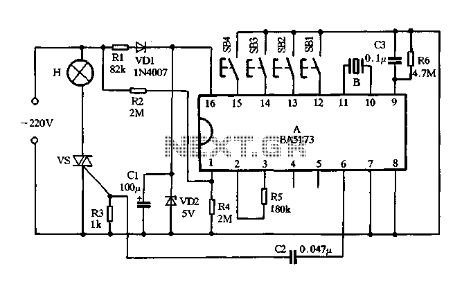
The circuit consists of components VDI, VD2, R1, and C1, which together form a resistance voltage half-wave rectifier circuit. This configuration produces a DC output voltage of 5V to supply various devices. R2 is utilized to provide an AC...
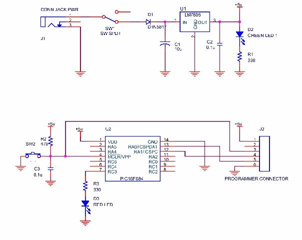
A simple program that will blink an LED. All that is required is a basic JDM programmer, and the setup is ready to go. The circuit requires a power supply, and while a good power generator is recommended, a...
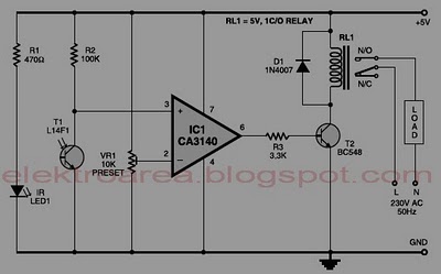
Typically, home appliances are controlled using switches, sensors, and similar devices. However, physical interaction with switches can pose safety risks in the event of a short circuit. The circuit outlined here eliminates the need for physical contact to operate...
The control voltage is fed into the first half of a 1458 op-amp, this stage inverts the signal and sets the offset and gain for the right channel gain control circuit. This signal is then fed into the second...
A thermistor is utilized in the circuit for heat sensing, while two 5K variable resistors are incorporated to calibrate the circuit for activating the relay at the desired temperature. The inclusion of a 1N4007 diode across the relay serves...