
police lights
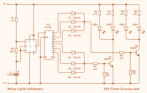
The circuit begins with the 555 timer, which is set up in astable mode. In this mode, the timer oscillates continuously, generating a square wave signal at a specific frequency determined by the values of two resistors and a capacitor connected to it. The output at Pin 3 alternates between high and low states, creating a periodic signal.
This output signal is fed into the clock input of the CD4017 decade counter. The CD4017 is a versatile counter that counts from 0 to 10 and provides a high signal at one of its ten output pins for each clock pulse it receives. As the 555 timer generates a square wave, each rising edge of the signal increments the count of the 4017, sequentially activating its output pins.
The outputs of the 4017 are connected to a series of light-emitting diodes (LEDs). Each time the 4017 counts up, it turns on the corresponding LED while turning off the previous one. This creates a visual effect where the LEDs appear to light up in sequence. The timing of the 555 timer can be adjusted by changing the resistor and capacitor values, allowing for control over the speed of the LED sequence.
Overall, this circuit effectively demonstrates the use of a 555 timer in conjunction with a decade counter to create a simple LED chaser effect. The design is straightforward, making it suitable for educational purposes as well as practical applications in decorative lighting displays.This circuit uses a 555 timer which is setup to both runn in an Astable operating mode. This generates a continuous output via Pin 3 in the form of a square wave. When the timer`s output changes to a high state this triggers the a cycle on the 4017 4017 decade counter telling it to output the next sequential output high. The outputs of the 4017 ar e connected to the LEDs turning them on and off. 🔗 External reference
Related Circuits
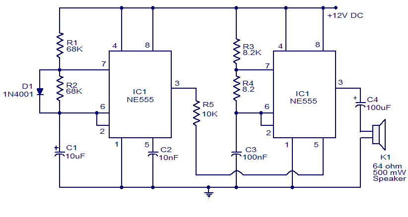
A variety of electronic circuits utilize the NE555 timer integrated circuit (IC). The circuit diagram presented illustrates a police siren based on two NE555 timer ICs, both configured as astable multivibrators. The circuit operates on a DC voltage supply...

This circuit utilizes low-voltage AC to power a string of approximately 50 bi-color LEDs, with two LEDs connected in inverse parallel. The power supplied to the LEDs is managed by a Triac and two optocouplers, whose phototransistors are also...

From 230 V AC a DC supply of + 5 V is obtained. The power supply is given to the other blocks. The pulse generator at a particular frequency generates the clock pulses. The clock pulses are counted by...

A circuit that can automatically turn off the headlights or lamps of a vehicle after a preset time. This light switching circuit is constructed using a 555 timer integrated circuit (IC). The described circuit utilizes the 555 timer IC in...
The task involved testing the capacitive properties of food by connecting various edibles to an Arduino. This project, known as BeetBox, was developed by Scott Garner, a student at NYU-ITP, who designed an innovative musical instrument that uses beets...

This simple Christmas LED lights decoration circuit allows for the creation of an 18 LED flasher to adorn a Christmas tree. The circuit incorporates white, blue, and red LEDs that flash in a festive pattern. The circuit is designed to...