
Police siren
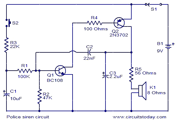
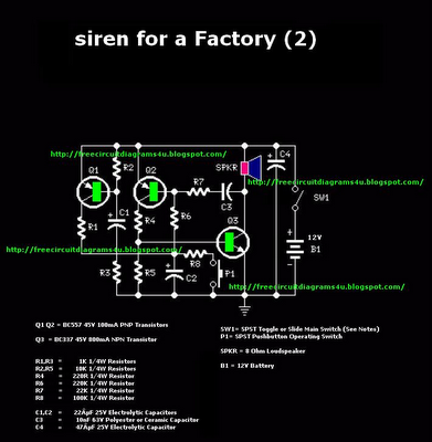
The described circuit operates as an astable multivibrator, creating a square wave output that simulates a siren sound. The timing of the sound is governed by the charge and discharge cycles of capacitors C1 and C2, which are integral to the oscillation process.
Transistor Q1 functions as a primary switch that controls the charging of capacitor C1. When S2 is pressed, Q1 enters saturation, allowing current to flow through it and charging C1. The gradual turn ON of Q1 is facilitated by the RC time constant determined by the values of C1 and the associated resistors. The discharge phase occurs when S1 is released, leading to a gradual decrease in Q1's conduction, which is also influenced by the time constant of the discharge path.
Transistor Q2 acts as a secondary switch that is controlled by the voltage across C2. As Q1 turns ON and the collector voltage drops, Q2 is activated, allowing C2 to charge. The relationship between Q1 and Q2 creates a feedback loop that enhances the oscillation effect. The coupling of C2 to the base of Q1 ensures that small changes in Q2's state affect Q1, leading to a cascading effect that results in the alternating ON and OFF states of both transistors.
The sound output of the circuit is characterized by a frequency that varies based on the capacitance and resistance values in the circuit. The rise and fall of the tone are directly related to the charging and discharging rates of C1. The design can be further refined by adjusting the component values to achieve the desired sound frequency and volume. Overall, this circuit is a practical example of using transistors and capacitors to generate an audio signal with a specific modulation pattern, suitable for alarm systems or sound effects in various electronic applications.The circuit given here produces an alarm similar to the police siren. When you press the push button switch S2 capacitor C1 will charge and this will make the transistor Q1 to ON slowly. When the switch S1 is released the C1 will discharge and the transistor Q1 will become OFF slowly. When the Q1 is switched ON, its collector voltage falls and mak es the transistor Q2 ON. The capacitor C2 will be charged almost to full supply voltage. This results in an increase in the collector-emitter voltage of Q2. This change in voltage is coupled to the base of Q1 via the capacitor C2. As a result the transistor Q1 comes slightly out of saturation. As a result the collector voltage of Q1 drops and makes the Q2 more OFF. This action continues until both transistors become OFF. Then the capacitor C2 discharges, and transistor Q1 will be switched ON again to start a new cycle. When the capacitor C1 is charged the tone will rise and when the capacitor C1 is discharging the tone will fall. 🔗 External reference
Related Circuits
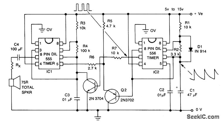
This circuit is a sound generator designed to simulate the siren of a British police car. It utilizes two timer IC 555 components to produce sound frequencies. The operation of the circuit involves the 555 timer on the right,...
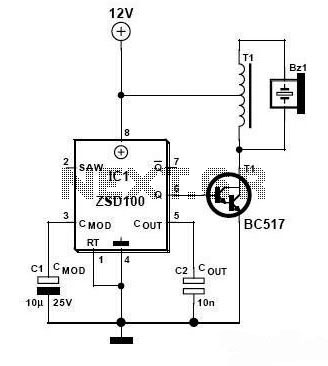
Zetex Semiconductors offers a siren driver integrated circuit (IC) known as the ZSD100, which is designed for use in alarm systems for vehicles and model crafts. By incorporating just a few additional components, as illustrated in the accompanying diagram,...
The signal begins at a low frequency, increases over approximately 1.15 seconds to a high frequency, pauses for about 0.35 seconds, and then starts to rise again from a low frequency, continuing this pattern indefinitely. The described signal exhibits a...
This is a powerful siren circuit diagram. This circuit can provide significant support for alarm systems, enabling users to achieve optimal results. The siren circuit is designed to produce a loud sound for alerting purposes, commonly used in security systems,...
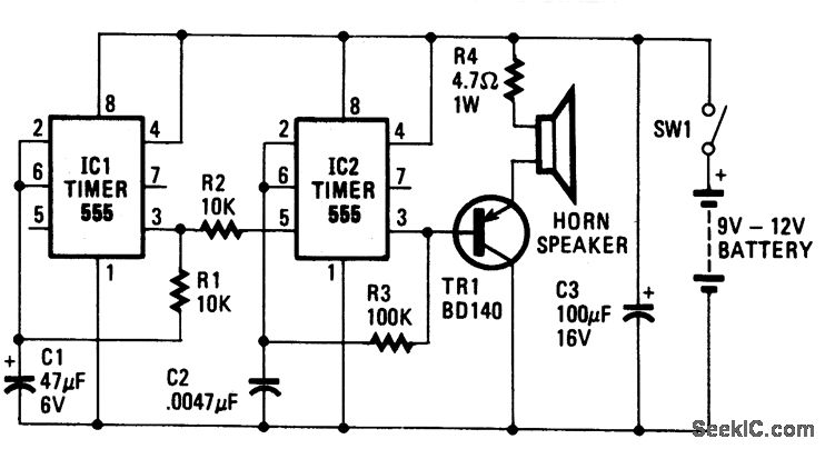
The oscillator based on IC2 generates sound, with its output linked to the base of TR1, which amplifies the signal to drive the speaker. Resistor R4 is included to limit the current through TR1 to a safe level. The...
This alarm siren circuit produces a warbling sound, suitable for use in toys or security alarms. The circuit employs two 555 IC oscillators. The first oscillator generates the audio frequency, while the second oscillator creates a modulating signal. This...
Warning: include(partials/cookie-banner.php): Failed to open stream: Permission denied in /var/www/html/nextgr/view-circuit.php on line 713
Warning: include(): Failed opening 'partials/cookie-banner.php' for inclusion (include_path='.:/usr/share/php') in /var/www/html/nextgr/view-circuit.php on line 713