
Police sirens sound with ic 555

The siren sound commonly used in emergency vehicles is generated by a specialized audio system designed to capture attention quickly and effectively. This system typically consists of a siren control unit, a power amplifier, and one or more loudspeakers.
The siren control unit generates the audio signal, which can be a continuous tone or a modulated sound pattern, designed to be distinctive and penetrating. The control unit is often microcontroller-based, allowing for programmable sound patterns that can be adjusted depending on the situation.
The power amplifier boosts the low-level audio signal from the control unit to a level suitable for driving the loudspeakers. This component is crucial, as it ensures that the sound can reach a significant distance, alerting pedestrians and other drivers to the presence of an emergency vehicle.
The loudspeakers used in siren systems are typically designed to handle high power levels and have a wide frequency response to reproduce the siren sound accurately. They are often mounted on the roof of the vehicle to maximize sound dispersion.
Additionally, modern siren systems may incorporate features such as automatic activation based on vehicle speed or proximity to certain locations, enhancing their effectiveness in alerting others during emergencies. The integration of these components into a cohesive system is essential for ensuring that the siren performs reliably in critical situations.Many a person will might excited with siren sound the all that ever hear. Because we will hear when there is an accident emergency event. But ever suspect that.. 🔗 External reference
Related Circuits
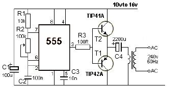
This 12V power inverter circuit can be utilized to power small devices that require 240 volts. It is particularly advantageous for operating 240-volt appliances using a 12-volt car battery. Unlike typical feedback oscillator inverters, this design employs a 555...
The primary components of this doorbell circuit include two NE555 timer integrated circuits (ICs). When the switch S1 is pressed momentarily, the loudspeaker emits a bell tone for the duration determined by the time period of the monostable multivibrator...
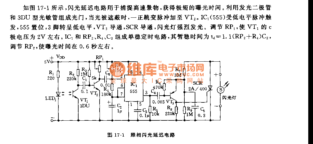
As shown in figure 17-1, the camera flash delay circuit is designed to capture high-speed scenes, allowing for very short exposure times. The light gate consists of a luminous diode and a 3DU type photosensitive tube. When the light...
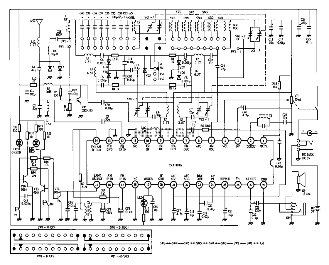
Desheng 1012 is a 12-band radio circuit diagram that covers FM, MW, SW, and TV sound frequencies. The Desheng 1012 radio circuit is designed to receive a wide range of frequencies across multiple bands, including FM (Frequency Modulation), MW...
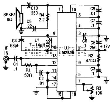
An LM2808 performs IF amplification of the 4.5-MHz sound subcarrier, limiting, detection, and audio amplification. If the center frequency must be changed, then change L1/C4. Audio output is 0.5 W. R3 is the volume control. The LM2808 is an integrated...
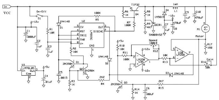
Speed regulation is achieved by monitoring the motor current with resistor R17 and utilizing it as positive feedback to offset motor resistance losses. The gain potentiometer should be adjusted to just below the threshold where motor speed begins to...