RF2126 high efficiency amplifier for 2.45 GHz ISM
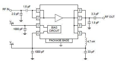
The RF2126 high-power linear amplifier IC, manufactured by RFMD, can be utilized to design a simple yet highly efficient amplifier for 2.45 GHz ISM applications, including WLAN and POS terminals. This component also serves as the final stage in digital PCS phone transmitters that require linear amplification within the frequency range of 1800 MHz to 2500 MHz. The device is self-contained, with the exception of the output matching network and power supply feed line. This RF power amplifier typically generates an output power level of 1W.
The RF2126 amplifier is designed for optimal performance in various applications, providing linear amplification that is essential for maintaining signal integrity in high-frequency communications. The device incorporates advanced technology to ensure minimal distortion and high efficiency, making it suitable for both consumer and industrial applications.
To implement the RF2126 in a circuit, the following components and considerations are essential:
1. **Power Supply**: The amplifier requires a stable power supply capable of delivering the necessary voltage and current. The typical operating voltage for the RF2126 is around 5V, and the power supply should be designed to handle the peak current demands during operation.
2. **Output Matching Network**: The output of the RF2126 must be matched to the load impedance (usually 50 ohms) to maximize power transfer and minimize reflections. This can be achieved using a combination of inductors and capacitors arranged in a matching network. The design of this network will depend on the specific load characteristics and the desired frequency response.
3. **Input Signal Conditioning**: The input signal should be conditioned to ensure that it meets the required amplitude and bandwidth specifications for the RF2126. This may involve using additional amplifiers or filters to prepare the signal for amplification.
4. **Thermal Management**: Given the power levels involved, adequate thermal management is crucial. The RF2126 should be mounted on a PCB with sufficient copper area to dissipate heat, and additional heat sinks may be required to maintain optimal operating temperatures.
5. **PCB Layout Considerations**: The layout of the printed circuit board (PCB) is critical for high-frequency performance. Careful attention should be paid to trace lengths, impedance matching, and minimizing parasitic capacitance and inductance. Using a ground plane and maintaining short connections to the power supply and output network will help achieve better performance.
6. **Testing and Tuning**: After assembling the circuit, testing and tuning may be necessary to optimize performance. This can involve adjusting the matching network components and verifying the output power and linearity using appropriate RF test equipment.
By following these guidelines, the RF2126 can be effectively integrated into various RF applications, delivering reliable performance in demanding environments.Using the RF2126 high-power, linear amplifier IC manufactured by RFMD can be designed a very simple and high efficiency amplifier for 2. 45 GHz ISM applications such as WLAN and POS terminals. The part will also function as the final stage in digital PCS phone transmitters requiring linear amplification operating between 1800MHz and 2500MHz.
The de vice is self-contained with the exception of the output matching network and power supply feed line. This RF power amplifier produces a typical output power level of 1W. 🔗 External reference
Warning: include(partials/cookie-banner.php): Failed to open stream: Permission denied in /var/www/html/nextgr/view-circuit.php on line 713
Warning: include(): Failed opening 'partials/cookie-banner.php' for inclusion (include_path='.:/usr/share/php') in /var/www/html/nextgr/view-circuit.php on line 713
