
switching power supply stability cipher scheme
In the design of a switching power supply, careful consideration must be given to the feedback loop to ensure that the system remains stable across a range of operating conditions. The feedback loop's design should account for the phase shifts introduced by various components, including the control amplifier and the switching elements. The selection of components such as the TL431 for error amplification and the optocoupler for isolation is critical, as these components directly influence the performance and stability of the power supply.
The PWM control strategy plays a significant role in regulating the output voltage by adjusting the duty cycle based on the feedback received. This adjustment must be finely tuned to maintain the desired output voltage while avoiding excessive phase shifts that could lead to instability. The integration of voltage comparators with compensation networks helps to minimize the effects of load transients and variations in input voltage, which can otherwise destabilize the system.
Furthermore, the analysis of phase margin and gain margin provides insight into the system's stability. A phase margin greater than 45 degrees is typically sought to ensure robustness against variations, while a lower phase margin of 30 degrees may be acceptable in scenarios involving significant load or input voltage fluctuations.
The harmonic analysis of the system, particularly in response to disturbances, is essential for understanding how the system behaves under non-ideal conditions. The detection of harmonic components can inform design adjustments to mitigate potential instability and improve overall performance.
In summary, the design of a switching power supply requires a comprehensive understanding of feedback control principles, component selection, and stability analysis to achieve reliable and efficient operation.As everyone knows, any closed loop system is unit gain to noise temperature ratio l in the gain to noise temperature ratio, the phase shift that and inside varies with frequency is at the time of the 360 deg, there will all not be possibility in this closed loop control system. So there is a loop-locked feedback control system in almost all the sw itching power supplies, thus can obtain better characteristic. In shouldering the feedback system, the control amplifier connection mode has introduced 180 quadrature 90 willfully, if the phase place feedbacked keeps within 180 degrees, it is always stable to control the cycle. Certainly, the situation be will existed in reality, because various switch delay time and impedance lead extra phase shift into, if does not adopt the appropriate cycle to compensate, this kind of phase shift will cause the unstability of switching power supply too.
The index of weighing the stability of the switching power supply is phase margin and gain margin. Phase margin refers to: The correspondent phase place when the gain to noise temperature ratio drops to 0dB. The gain margin refers to: The phase place, for the correspondent gain magnitude actually decay at zero hour.
While designing the switching power supply actually, consider the gain margin only while designing the anti exciting converter, while designing other converters, seldom use the gain margin. In the switching power supply design, there are two to act on phase margin separately: First, the dynamic procedure that can appear in the step change of load with the damping converter; Another function change as yuans of device parameter, permitted security system steady still.
Phase margin can only be used for guaranteeing The dwarf signal is steady . While supporting the step change, it will entered the big signal will be steady that the power is inevitable Range. We think at room temperature, reference input, normal loading condition in the project, the phase margin requirement of the cycle is greater than 45 degrees.
Under various parametric variations and error situations, this phase margin is enough to guarantee the system is steady. Variation on load or input voltage range, change very large, consider load and the intersection of input voltage and lower cycle and phase margin should greater than 30 in all.
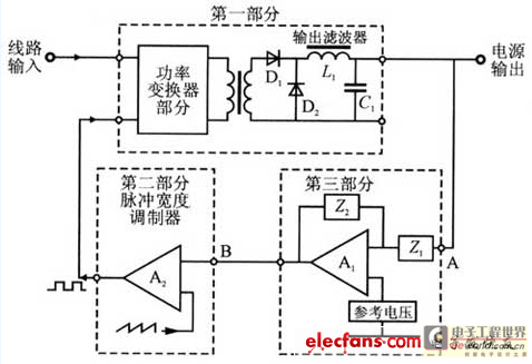
As Fig. l shows in order to turn on or off the square frame synoptic diagram of power supply control, the power supply control cycle of switch is formed by 3 following parts. 3Sample and control comparison enlarge part, include output voltage sample, compare, amplify mainly if TL431, the error is enlarged and transmitted such as the photoelectric coupler The intersection of PWM and Integrated voltage comparator compensation of amplifier these design maximum the intersection of decision and the intersection of switching power supply and system stability under integrated circuit, it is focal point and difficult point designed.
As shown in Fig. 1, if introduce the disturbance wave at node A. The energy distribulion that this rectangular wave includes lists harmonic component once very limitlessly. If detect constantly the increscent harmonic wave is being responded to, can find out gain to noise temperature ratio and phase shift change with increase of the frequency for true system pair.
If lay the gain to noise temperature ratio in a certain frequency and equal l and the general extra phase shift adds 180 quadrature 90 that is originally presumed for 180 degrees this phase shift, total phase shift is measured as 360 deg, Will then have input end where sufficient energy will be returned to the system, and the phase place is the same as original phase place, interfere with keeping going down, the system will shake under this frequency. As shown in Fig. 2, generally, the control amplifiers will all adopt the components and parts Z2 of feedback compensation to reduce the gain
🔗 External reference
Related Circuits
This circuit is designed for high current applications using nickel-cadmium rechargeable batteries, and it can also function as a general low-voltage DC power supply. The circuit consists of a charging section and a DC output section. K2 serves as...
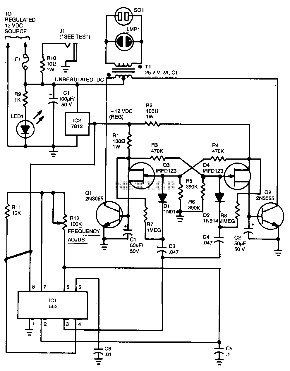
Capacitor C5 and potentiometer R12 determine the frequency of the output signal at pin 3 of IC1, the 555 oscillator. The output signal is differentiated by C3 and C4 before it is input to the base of power transistors...
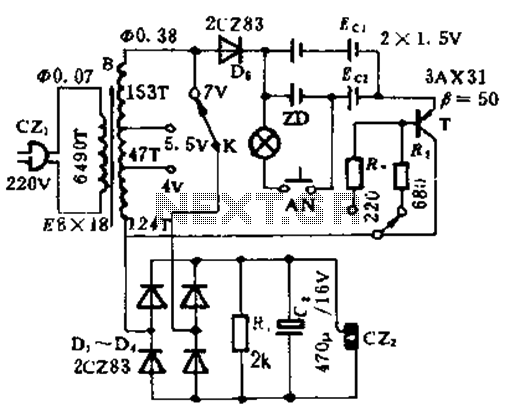
This circuit functions as a night lamp when a wall mains socket is unavailable for plugging in a continuously operating small neon lamp device. To minimize battery consumption, it utilizes a single 1.5V cell, and a simple voltage doubler...
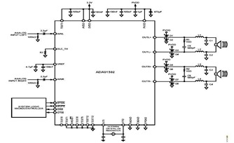
This is a typical stereo application circuit schematic of the ADAU1592, a 2-channel, bridge-tied load (BTL) switching audio power amplifier. The ADAU1592 can be utilized in flat panel televisions, PC audio systems, and mini-component applications. The ADAU1592 is designed to...
A 50W isolated forward-converter switching supply for telecom applications is described. Most aspects of the design are discussed. The 50W isolated forward-converter switching supply is engineered to meet the specific demands of telecom applications, where reliability and efficiency are paramount....
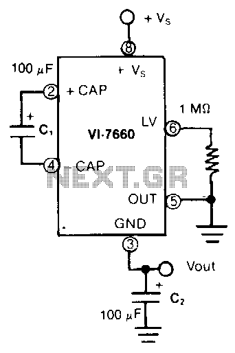
In this application, the VL-7660 is configured as a voltage splitter. The normal output pin is connected to ground, while the normal ground pin serves as the output. The switches facilitating charge pumping are bidirectional, allowing for reverse charge...