
switches Default-on latch-off MOSFET power switch

The circuit design described involves a typical latch configuration using N-channel and P-channel MOSFETs to achieve a power control mechanism. The N-channel MOSFET (M1) is employed to allow current flow when the gate is driven high by the initial capacitor charge. The use of a BS170 as M1 indicates a preference for a smaller MOSFET with lower threshold voltage, suitable for low-power applications.
The P-channel MOSFET (M2) serves as the main switch for the power supply to the load. When the gate of M2 is pulled low by the conduction of M1, it allows the voltage to pass through to the load, effectively powering the circuit. The voltage divider formed by resistors R3 and R2 plays a crucial role in maintaining the gate voltage of M2 at a level that keeps it conducting even after M1 is turned off.
The transition from the "on" state to the "off" state is initiated by the OFF signal, which, when driven low, reduces the gate voltage of M1, causing it to stop conducting. This action leads to R1 pulling the gate of M2 high, thereby turning off M2. The charge stored in C1 ensures that the circuit remains off despite changes in the OFF signal, providing a latching effect.
One critical aspect to consider is the leakage current that may flow through the components when the circuit is in the "off" state. This leakage can drain the battery over time, particularly concerning for rechargeable lithium polymer (LiPo) batteries, which can be damaged by over-discharge. Therefore, it is advisable to implement a mechanism to periodically check the battery voltage or to include a timer circuit that can automatically re-enable the circuit after a predetermined period.
Regarding the potential for oscillation, the circuit may oscillate if there are insufficient time constants involved with the capacitor and resistors, or if the feedback from the load induces instability. Proper component selection and values must be chosen to ensure stable operation without unintended oscillation.
Finally, the system should automatically turn on from a zero state when power is applied, provided that the initial conditions allow for the capacitor to charge sufficiently to turn on M1. Careful consideration of the timing and threshold voltages of the MOSFETs is essential to ensure reliable operation in all intended scenarios.It should default on when first connected, but if a particular signal goes high for a small amount of time (say, 10 microseconds, ) then it should turn off, and stay off. It`s the "default on" that gives me trouble. The closest I can get is something like this: From null, "OFF" is floating. Supply 15V, and the capacitor starts out acting like a bit of wire, which pulls the M1 N-channel gate high, which makes the N-channel conduct
(I`m likely to use a BS170, not the IRF on the schematic. ) That pulls the gate of the P-channel M2 low, which makes it conduct. That, in turn provides voltage into R3/R2 divider that keeps the circuit latched open. Now, when OFF goes low-impedance to ground, it will turn off M1, and thus R1 will pull the M2 gate high, and M2 will turn off. Because C1 already has a charge, the system will now stay with M2 turned off even if the OFF signal goes high impedance again (which it will, because it`s a MCU output eventually powered by the SWITCHED voltage.
) While off, the leakage through C1 and the leakage through R1/M1 (and, I guess, leakage through M2 and the entire powered subsystem) will still draw a little bit on the battery, so if it`s a LiPo, I shouldn`t leave it in that state forever or it will die, but as a safeguard for a hobby robot, I think it might work. Is this correct, or am I getting something wrong Will the system oscillate when the "off" is triggered Will the system automatically turn on from "zero" as intended
🔗 External reference
Related Circuits
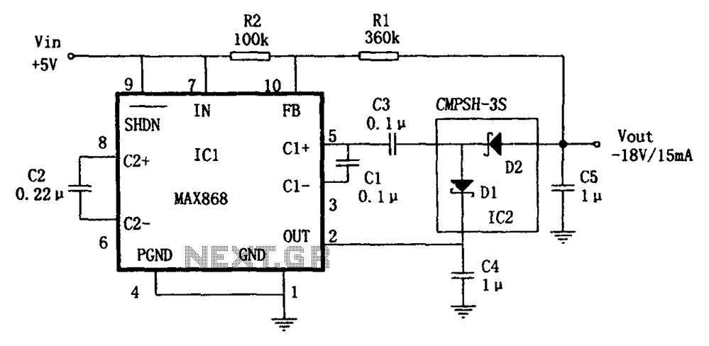
The circuit utilizes the IC1 MAX868 and CMPSH-3S to create a quadruple voltage DC/DC converter power supply. The IC1 MAX868 is an inverting charge pump regulator integrated circuit that can generate an output voltage of up to -2VIN, with...
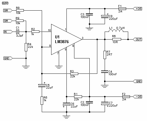
The supply voltage should be about +/- 35 Volts at full load, which will let this little guy provide a maximum of 56 Watts (rated minimum output at 25 degrees C). To enable maximum power, it is important to...
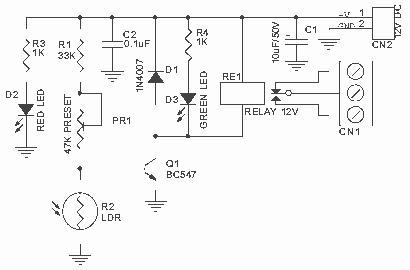
Light Sensitive Switch is a simple project which operates a relay when the light falling on the LDR goes below a set point. More: Input - 12 V @ 55 mA Relay output - NC-C-NO Onboard preset to set the level Power-On...
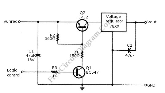
Logic power control of an analog regulator can be useful in applications where a digital circuit or controller needs to manage a power source, such as in EEPROM programmers or other power control systems. This circuit provides ON-OFF control...
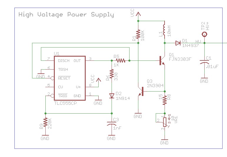
The design involves using a 555 timer as an oscillator in the high voltage power supply section. There is a query regarding the possibility of altering the design to utilize an output from a microcontroller to generate an oscillating...
By combining a current-reuse amplifier and a switch-based mixer, a dual-band receiver front end offers excellent performance with extremely low power consumption. The dual-band receiver front end integrates a current-reuse amplifier and a switch-based mixer to achieve high performance while...