
PowerSmart Solar Speeder, V2
The described circuit utilizes a bipolar transistor as a motor driver, which is particularly suitable for applications such as solar-powered vehicles in competitions. The design incorporates a 1381E voltage trigger, which activates at a threshold of 2.4V, ensuring that the motor operates efficiently within the voltage range provided by solar cells.
The circuit consists of a total of 10 components, which includes the motor itself. This is an increase from the standard stock circuit, which typically comprises only 6 components. However, the additional components are justified by the enhanced performance and efficiency achieved with this design. The output transistor is engineered to maintain a low voltage drop across its terminals, ensuring that maximum voltage is delivered to the motor under all load conditions. This is critical for maintaining performance, especially in applications where power efficiency is paramount.
Furthermore, the circuit is designed to minimize wasted base current, a common issue in transistor switching applications. By optimizing the base current, the circuit reduces energy losses during operation, which is particularly beneficial in solar-powered systems where every milliampere counts. The lack of losses during the charging phase contributes to the overall efficiency of the motor driver, allowing for longer operation times and improved performance in competitive scenarios.
In practical terms, this design can be evaluated by measuring the base current under various load conditions, demonstrating the significant reduction in wasted energy compared to traditional designs. This performance improvement makes the bipolar transistor motor driver an excellent choice for solar roller competitions, where efficiency and reliability are crucial for success.This must be the most efficient bipolar transistor motor driver design for this application and I recommend it for the solar roller competitions. A 1381E is used to trigger at 2.4V. While it takes a total of 10 components plus motor compared to the stock circuit`s 6 components, you will clearly get better performance compared to a stock Solar Roller/Speeder circuit.
There are no losses during charging and the output transistor has a guaranteed low voltage drop under all motor load conditions while the normally wasted base current is absolutely minimized. To demonstrate the difference in wasted base current, measure t 🔗 External reference
Related Circuits
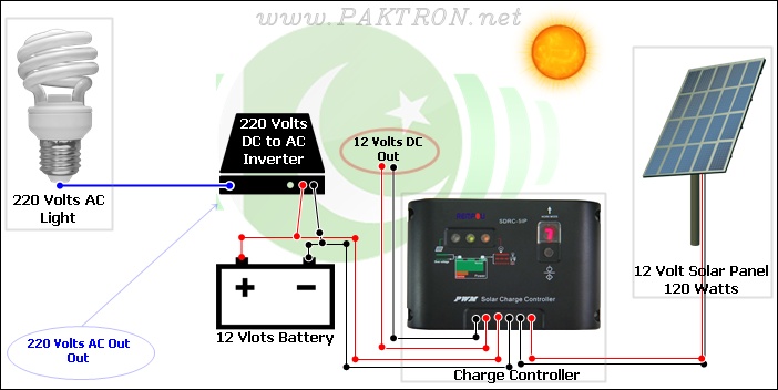
A solar charge controller is an electronic device used in solar system installations to regulate the amount of charge directed toward a battery from a solar panel. Charge controllers come in various types and ratings. The term "charge controller"...
The LED arrangement in the LM339 circuit consists of two rows of three LEDs, with each LED connected in parallel. The two rows are connected in parallel but with reversed polarity. The sensor array is composed of three west-facing...
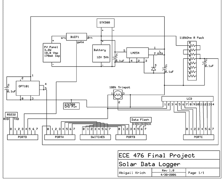
My project is a self-powered solar data logger. Put out in the sunlight, it will measure the light level and log this to memory to be later downloaded to a computer. The system is powered by a small solar...
The simplest current-to-voltage (I to V) converter is a basic resistor. However, the disadvantage of this simple configuration is that it presents a nonzero impedance to the input current source. The I to V converter is an essential circuit in...
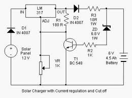
By adjusting the Adjust pin, the output voltage and current can be regulated. A variable resistor (VR) is connected between the Adjust pin and ground to achieve an output voltage of 9 volts to the battery. Resistor R3 limits...
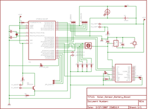
The project involves enhancing the Botanicalls system by integrating a solar panel that functions as both a light sensor and a battery charger for each plant. The complete circuit schematic is provided above, along with detailed images illustrating the...
Warning: include(partials/cookie-banner.php): Failed to open stream: Permission denied in /var/www/html/nextgr/view-circuit.php on line 713
Warning: include(): Failed opening 'partials/cookie-banner.php' for inclusion (include_path='.:/usr/share/php') in /var/www/html/nextgr/view-circuit.php on line 713