
Power Supply
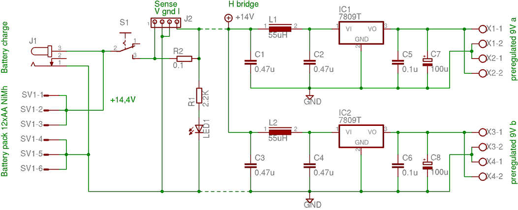
The power supply system is designed to deliver reliable energy to various components of the robot, ensuring optimal performance during operation. The aluminum enclosure provides both physical protection and efficient thermal management for the internal components. The NiMH cells are selected for their balance of energy density, cycle life, and safety, making them suitable for robotic applications.
The use of two lines of preregulators enhances the overall reliability of the power distribution by isolating different sections of the circuit. This decoupling minimizes the risk of voltage fluctuations affecting sensitive components and allows for better load management. Each preregulator is designed to maintain a steady output voltage, accommodating the varying power demands of the robot's circuitry.
The front section of the circuit plays a critical role in user interaction and maintenance. The recharging socket enables easy access for battery replenishment, while the on-off switch provides a straightforward method for powering the robot on and off. The signaling LED serves as an important visual indicator, providing feedback on the power status of the system.
Overall, the power supply system is a well-thought-out design that integrates essential features for both functionality and user convenience, ensuring that the robot operates efficiently and reliably.As described in the block diagram page, this is the system that provides power supply for all the circuitry of the whole robot. In the aluminum box there are the NiMH cells and all the circuits already described. There are two lines of preregulators to better decouple the boards and to have more power available. The dotted lines indicate the divis ion between the front part of the circuit and the rear one. The first one contains recharging socket, the on-off switch and the signalling LED. 🔗 External reference
Related Circuits
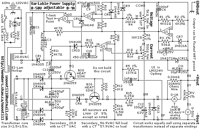
A reverse-engineered circuit diagram of a high-end commercial variable laboratory power supply. This unit is constructed using a standard operational amplifier and readily available components. While the design employs a single transformer with dual output windings, it can also...
Most peripherals that interface with a PC utilize a USB port. The computer's power supply circuit, specifically the switched-mode power supply (SMPS), is designed to provide constant power to all internal components. However, when external peripherals that require a...
Since my page was first posted, I have received a number of emails asking about a high current power supply. I looked around, but couldn’t find one that was suitable. So, I designed this. It is a linear supply,...
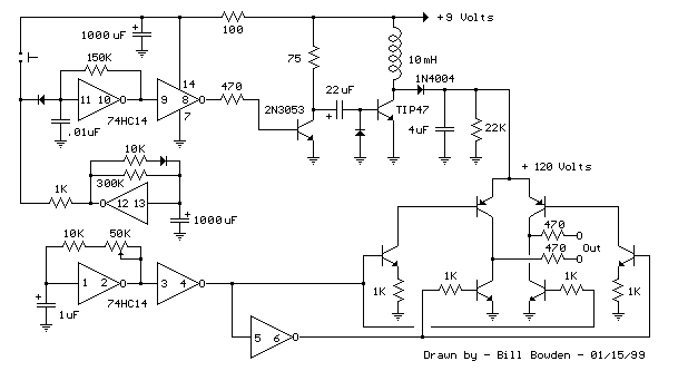
The telephone ring generator described generates the necessary aerial voltage using a simple switched-mode power supply (SMPS). It incorporates a CMOS Schmitt Trigger-based oscillator, a 10 mH inductor, a high-voltage switching transistor (such as the TIP47 or another high-voltage,...
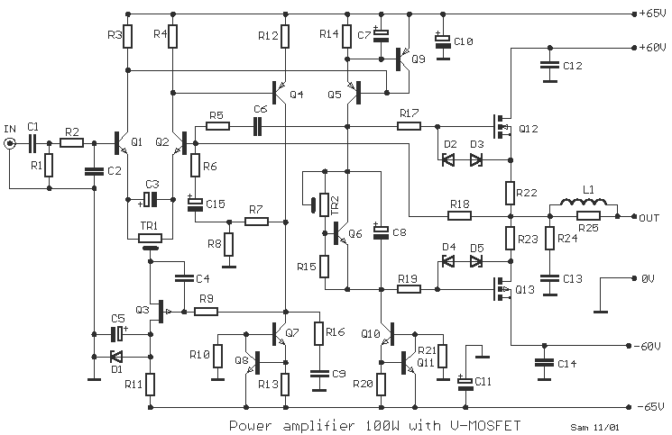
One still designing that it uses in the exit transistor of technology V-mosfet. This transistors to us offer a lot of virtues concerning the simple bipolar transistors, as high speeds, thermic stability, low distortion etc. Beyond this circuit use...
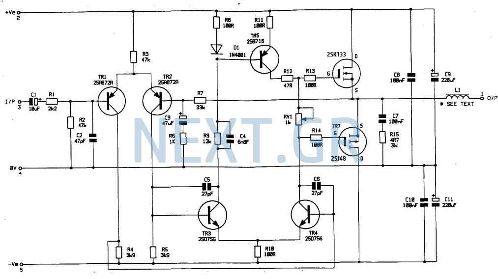
In my opinion that is the best buildable high power amplifier out there. Quality of sound is just remarkable. This is a real bomb proof amplifier like the best Valve amps. Power supply circuit is also shown. Now lets...